




















How should a 261 kWh energy storage battery cabinet be matched with a PCS (power conversion system) inverter?
Oct 22, 2026
Leave a message

A 261kWh energy storage battery cabinet is a common configuration for applications such as C&I (commercial and industrial) energy storage, self-consumption of solar power, peak-valley arbitrage, demand management, and microgrid projects. Ensuring the safe and stable operation of such a cabinet requires more than just selecting a Power Conversion System (PCS) based solely on the 261kWh capacity. Instead, one must comprehensively consider factors including the battery's nominal voltage, maximum charge/discharge current, continuous charge/discharge rate, the PCS's DC voltage range, AC-side rated power, system efficiency, grid-connection requirements, and energy management strategies.
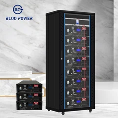
For BLOO POWER's 261kWh C&I energy storage battery cabinet, the core of PCS selection lies in establishing a power match between the battery's DC side and the grid's AC side. While capacity determines the amount of energy the system can store, the PCS power rating dictates the speed at which the system can charge or discharge; these two elements must be designed in coordination. For instance-provided that the battery's voltage, current, and BMS (Battery Management System) control requirements are met-it may be feasible to configure the system with a 125kW, 130kW, or 150kW PCS. However, the final model must be determined based on specific battery parameters and project operational objectives, rather than being decided by the capacity figure alone.

Understanding the Matching Logic Between a 261kWh Battery Cabinet and a PCS
"261kWh" refers to the nominal energy capacity of a battery system, while "kW" denotes the continuous active power output (or conversion capacity) of a Power Conversion System (PCS); these are distinct parameters. A 261kWh battery cabinet can be paired with a PCS of varying power ratings. The choice affects the system's charge/discharge rates, duration of continuous discharge, the current load on the batteries, and the overall project economics. For instance, theoretically, a 261kWh battery discharging continuously at 130.5kW would yield a nominal discharge duration of approximately 2 hours, whereas discharging at 261kW would result in about 1 hour. However, these are merely theoretical values derived by dividing capacity by power; they do not represent the actual, usable discharge duration. Factors such as the battery's allowable C-rate, the usable State of Charge (SOC) window, conversion losses, and auxiliary power consumption all influence the final outcome. Similarly, energy storage modeling documentation from the U.S. National Renewable Energy Laboratory (NREL) treats battery capacity, maximum charge/discharge power, battery voltage, and converter efficiency as separate design parameters.
For BLOO POWER's 261kWh commercial and industrial (C&I) energy storage cabinets, it is advisable to clarify three key points: First, what are the actual DC operating voltage and the maximum allowable charge/discharge current of the battery cabinet? Second, what continuous power output (in kW) does the client require, and for how long must it be sustained? Third, what is the intended application-photovoltaic (PV) self-consumption, peak-valley arbitrage, demand charge management, or microgrid support? Only by cross-referencing these requirements against the battery specifications, Battery Management System (BMS) limits, and the PCS technical manual can one determine the appropriate PCS power rating. Simply dividing 261kWh by an arbitrary "rule-of-thumb" factor is not a sound basis for procurement.
How is the PCS power for a 261 kWh energy storage battery cabinet initially calculated?
For example, assuming a nominal capacity of 261 kWh, a usable energy ratio of 90%, and a PCS DC-to-AC conversion efficiency of 97%, the usable DC energy would be approximately 234.9 kWh, and the energy deliverable on the AC side would be approximately 228 kWh. If a continuous discharge duration of 2 hours is desired, the theoretical average AC power would be approximately 114 kW; after accounting for engineering margins, one might consider a PCS rated at 125 kW or 130 kW. However, this is merely an illustrative example and does not imply that the BLOO POWER 261 kWh battery cabinet is confirmed to support these power levels. Final equipment selection must always be constrained by factors such as the battery's maximum current, minimum operating voltage, temperature-based derating, the PCS operating curve, and grid-connection requirements. NREL's energy storage modeling documentation also clearly distinguishes between nominal capacity, usable capacity, and power conversion losses; this distinction should be consistently applied in engineering design.
Theoretical Comparison of a 261 kWh Battery Cabinet Paired with PCS Units of Various Power Ratings
The following preliminary comparison is based on a nominal capacity of 261 kWh, assuming a 90% battery usable energy ratio and a 97% PCS DC-to-AC efficiency. The deliverable energy shown in the table-approximately 228 kWh-is intended solely to illustrate the relationship between capacity, power, and discharge duration; it does not represent guaranteed values for actual equipment.
|
PCS AC rated power |
Duration corresponding to nominal capacity |
Estimate the duration for AC deliverables |
Initial areas of application |
|
65kW |
4.02 hours |
3.51 hours |
Long-term energy management |
|
100kW |
2.61 hours |
2.28 hours |
Industrial and Commercial Load Shifting |
|
125kW |
2.09 hours |
1.82 hours |
Candidate Options for Two-Hour-Scale Projects |
|
130kW |
2.01 hours |
1.75 hours |
Higher-power industrial and commercial energy storage |
|
150kW |
1.74 hours |
1.52 hours |
Higher peak power demand |
|
261kW |
1.00 hours |
0.87 hours |
For high-rate designs, battery capabilities must be rigorously verified. |
It should be noted that the deliverable duration shown in the table is calculated by dividing the estimated AC energy by the AC rated power of the PCS, under the assumption that the equipment can continuously output this power without any additional power-limiting constraints. This calculation does not account for power limitations resulting from variations in the battery's state of charge (SOC), temperature-based derating, or power consumption by auxiliary systems. Therefore, for actual projects, the manufacturer's performance curves and the results of system acceptance testing should be used as the definitive reference.
Determining Whether the PCS Exceeds Battery Capacity Limits Using C-Rates
Once capacity and power calculations are complete, it is essential to verify the battery's charge/discharge C-rate. The C-rate represents the relationship between the battery's power and its rated energy capacity. For a 261 kWh battery cabinet, if the system permits a continuous charge/discharge rate of 0.5C, the theoretical DC power limit is 130.5 kW; if a 1C rate is permitted, the theoretical limit becomes 261 kW. However, these figures are merely the result of C-rate calculations and do not constitute a performance guarantee for a specific battery cabinet. The actual allowable C-rate must be determined based on the cumulative limitations of the battery cells, modules, busbars, contactors, fuses, thermal management system, and the Battery Management System (BMS)-relying solely on the promotional specifications of the individual cells is insufficient.
For instance, if a 261 kWh system allows for a maximum DC current of 250 A at a given operating voltage-say, 800 V-the corresponding DC power would be approximately 200 kW. If the voltage drops to 650 V, that same 250 A current would only correspond to 162.5 kW. This demonstrates that even if the current limit remains constant, a decline in battery voltage can reduce the maximum power output. For BLOO POWER's commercial and industrial (C&I) energy storage cabinets, engineers must evaluate the continuous charge current, continuous discharge current, short-term peak current, and the permitted duration for such peaks, subsequently incorporating these limits into the PCS control parameters. The final continuous power limit should be the lowest value permitted by the intersection of battery C-rate, current limits, voltage range, temperature conditions, and the operational capabilities of the PCS.
Verifying the Compatibility Between Battery DC Voltage and PCS Input Voltage Range
DC voltage compatibility is a critical factor-often overlooked-that can directly determine whether an energy storage system (ESS) cabinet (e.g., a 261kWh unit) can successfully start up when paired with a Power Conversion System (PCS). Before procurement, it is essential to obtain the battery cabinet's rated DC voltage, minimum operating voltage, maximum charging voltage, and overall operating voltage range. Simultaneously, one must verify the PCS's DC input operating range, start-up voltage, maximum allowable DC voltage, and maximum input current. The fact that a PCS is nominally rated for a specific high-voltage level does not guarantee compatibility with all high-voltage battery systems. Conversely, even if a battery cabinet's voltage falls within the PCS's permitted range, this does not automatically ensure that the current, power, and control interfaces are compatible.
For instance, if a battery cabinet has an operating voltage range of 650–850V and a candidate PCS has a normal operating range of 600–900V, they may be considered preliminarily compatible based on the voltage window alone. However, it is also necessary to confirm that the battery's maximum voltage does not exceed the PCS's absolute maximum input voltage, and that the voltage remains within the PCS's allowable limits even under conditions such as minimum State of Charge (SOC), low temperatures, or high-current discharge. (Note: These figures are hypothetical examples for illustrative purposes only and do not represent the actual specifications of BLOO POWER products.) If the battery cabinet utilizes multiple battery clusters in parallel, one must also verify voltage consistency across clusters, current distribution among branches, and the configuration of independent protection systems. During the design phase, priority should be given to a PCS capable of stable operation across the entire intended voltage range, rather than relying solely on a comparison of nominal voltage ratings.
Verifying PCS Capacity via DC Current Calculation
An appropriate PCS rated power does not automatically guarantee that the DC input current meets the requirements.
For example, if a PCS is required to absorb or output 130 kW of DC power, the theoretical current would be approximately 200 A at a DC voltage of 650 V, or approximately 162.5 A at 800 V. If the 130 kW figure refers to the AC output power of the PCS, conversion efficiency must be factored in; the required DC power from the battery side will exceed 130 kW, and the actual current will increase accordingly. For bidirectional PCS units, the rated current may differ between charging and discharging modes; therefore, equipment selection should not be based on parameters from a single direction alone.
In the system design for the BLOO POWER 261 kWh battery cabinet, it is essential to verify several parameters: the maximum DC current of the PCS, the current limits for each DC input port, the rated current of connectors, the specifications of DC circuit breakers and fuses, and the current-carrying capacity of the internal busbars and cables. If the PCS features multiple independent DC input ports, one must determine whether these ports can be connected in parallel, identify the current limit for each port, and ascertain whether separate battery clusters are required for each connection. Furthermore, factors such as cable length, ambient temperature, installation method, and voltage drop must be taken into account; one cannot simply divide the total rated DC input current of the PCS by the number of branches to determine the required cable gauge.
Selecting a 65kW, 100kW, 125kW, or 150kW PCS Based on Project Requirements
For a 261kWh commercial and industrial (C&I) energy storage battery cabinet, the rated power of the Power Conversion System (PCS) should be determined based on both the project's load profile and the battery's continuous discharge capability. A 65kW PCS is suitable for scenarios with lower instantaneous power requirements where a longer discharge duration is desired; a 100kW PCS is appropriate for many small-to-medium-scale C&I load-shifting projects; a 125kW or 130kW PCS can be considered for configurations approaching a two-hour nominal capacity; and a 150kW PCS offers higher AC output capacity, though it will shorten the theoretical discharge duration and requires the battery system to support a corresponding DC power output. The power ratings mentioned above are candidates for selection analysis and do not constitute compatibility certifications for this specific battery cabinet.
Selection should also account for PCS derating-which may occur due to high ambient temperatures, high altitudes, or abnormal grid voltage-as well as any project requirements for the continuous provision of reactive power. Since a PCS's rated apparent power is typically expressed in kVA and its active power in kW, the two are linked by the power factor. For instance, a 125kVA unit can theoretically achieve an active power output of 125kW at a power factor of 1.0; at a power factor of 0.9, the maximum active power output drops to approximately 112.5kW, provided the equipment is rated for operation at that power factor. Therefore, when selecting a PCS for a BLOO POWER project, one should not rely solely on the manufacturer's advertised maximum power figure; instead, it is essential to verify the rated active power, rated apparent power, reactive power adjustment range, and the corresponding derating curves.
Engineering Comparison of Different PCS Power Configurations
|
Comparison Items |
100kW PCS |
125kW PCS |
150kW PCS |
|
Corresponding duration of 261kWh nominal capacity |
2.61 hours |
2.09 hours |
1.74 hours |
|
Theoretical average power on the DC side, assuming 234.9 kWh of available energy |
100kW |
125kW |
150kW |
|
AC output energy estimated based on a 97% conversion efficiency |
≈228kWh |
≈228kWh |
≈228kWh |
|
Theoretical discharge duration on the AC side, calculated based on the aforementioned energy |
≈2.28 hours |
≈1.82 hours |
≈1.52 hours |
|
Key Design Considerations |
Continuous Discharge Duration and Load Demand |
Battery C-rate and Current Margin |
Battery High-Rate Capability, Derating, and Thermal Management |
The durations calculated based on AC output power in the table are intended solely for idealized comparison. In a real-world system, the relationship between battery-side power, the rated AC power of the Power Conversion System (PCS), and the actual output power is influenced by factors such as efficiency, control strategies, and operational limits; therefore, these theoretical durations should not be interpreted as the discharge durations guaranteed for the equipment.
Determining PCS AC-Side Specifications Based on Grid-Connection Method
The Power Conversion System (PCS) for a 261 kWh battery cabinet must not only be compatible with the battery's DC-side specifications but also align with the project's AC grid-connection requirements. First, it must be determined whether the project will connect to the grid via a 400V three-phase low-voltage connection or through a step-up transformer to a medium-voltage grid. Furthermore, factors such as grid frequency, grounding configuration, allowable grid-voltage deviation, short-circuit capacity, and the specific technical requirements of the local grid operator must be verified. For commercial and industrial (C&I) projects in Europe, this typically involves checking against 400V, 50Hz three-phase system standards and relevant grid codes; however, the final parameters must strictly adhere to the grid-connection approval issued for the specific project site. Requirements regarding active power control, reactive power regulation, low-voltage ride-through (LVRT), frequency response, and anti-islanding protection may vary by country or region.
Taking a 400V three-phase AC system as an example: if the PCS outputs 125 kW of active power at a power factor of 1, the theoretical line current is approximately 180 A; if the output is 150 kW at a power factor of 1, the theoretical line current is approximately 217 A. Actual equipment selection must also account for power factor, equipment efficiency, output voltage deviation, environmental derating, and protection coordination. If a step-up transformer is required, calculations must cover the transformer's rated capacity, impedance, temperature rise, inrush current, and protection settings. For BLOO POWER C&I energy storage projects, system integrators should provide a unified design encompassing the PCS, battery cabinets, AC distribution cabinets, transformers, and metering equipment. This ensures that while individual components-such as the PCS-may meet specific requirements, the overall grid-connection scheme also successfully passes regulatory review.
System Connection Architecture: PCS and Battery Cabinet
In a typical AC-coupled commercial and industrial (C&I) energy storage system, the battery cabinet is connected to a bidirectional Power Conversion System (PCS) via DC protection devices, while the PCS is connected to the facility's power distribution bus or a step-up transformer via AC switchgear. During charging, the PCS converts AC power into DC power to charge the batteries; during discharging, it converts the DC output from the batteries into AC power to supply loads or-subject to grid-connection permits-feed power back into the grid. The Battery Management System (BMS) monitors the status of individual battery cells and the overall system, manages charge/discharge limits, and issues operational permissions or restrictions. Meanwhile, the Energy Management System (EMS) develops charge/discharge schedules based on factors such as electricity pricing, photovoltaic (PV) generation forecasts, load demand, and grid dispatch requirements. Documentation from the National Renewable Energy Laboratory (NREL) regarding energy storage system architecture similarly characterizes the battery system, PCS, transformers, and monitoring/control equipment as integrated, interdependent components.
For the BLOO POWER 261kWh battery cabinet, project design documentation should clearly specify the DC positive and negative connections, main contactors, pre-charge circuits, fuses, insulation monitoring, emergency stop circuits, communication links, and maintenance isolation points. Specific configurations depend on the product design of both the battery cabinet and the PCS; it should not be assumed that all equipment follows the same wiring scheme. In multi-string systems, in particular, it is essential to verify that protection for each string is independent, that the PCS can identify the status of individual battery strings, and that any faulty string can be safely isolated. Once equipment arrives on-site, it must undergo polarity checks, insulation testing, communication verification, protection function validation, and a controlled initial charge/discharge test in accordance with the manufacturer's requirements-ensuring that the system is never operated at full capacity without prior commissioning.
Communication and Control Coordination among BMS, PCS, and EMS
Even if battery voltage, DC current, and PCS power capacity meet the requirements, the system may fail to start properly or achieve safe power control if the communication protocols between the BMS and the PCS are incompatible. Before project design, it is essential to verify the physical communication interfaces, protocol types, register mappings, data update cycles, control authority, and fault response logic. Common communication methods include CAN and Modbus (RTU/TCP); however, the specific protocol used by a given device must be confirmed via the manufacturer's documentation-compatibility cannot be assumed based solely on the name of the interface. In particular, it must be verified that the BMS can provide the PCS with critical real-time data, including voltage, current, State of Charge (SOC), maximum and minimum individual cell voltages, temperature, and the allowable charge/discharge power limits.
Regarding control strategy, the power commands issued to the PCS must not exceed the charge/discharge power limits currently permitted by the BMS. For example, if the EMS requests an output of 125 kW, but the BMS-due to low battery temperature, an SOC near the lower limit, or an abnormal cell voltage-restricts the allowable discharge power to 80 kW, the PCS must operate within this limit in accordance with the established control logic, rather than attempting to execute the original 125 kW command. Similarly, during charging, if the battery approaches its maximum SOC or the temperature exceeds the permitted range, the system must reduce the charging power or cease charging altogether. During the system integration phase, the project must include comprehensive testing for scenarios such as communication interruptions, BMS alarms, PCS faults, and emergency stops. It is also necessary to confirm the default system response in the event of a fault-whether it involves safely derating power, halting charge/discharge operations, or executing complete electrical isolation.
Selecting a PCS Based on Peak-Valley Arbitrage, PV Consumption, and Demand Management
The power rating of a Power Conversion System (PCS) should be determined by the project's operational objectives, rather than by simply pursuing the highest possible nominal value. For peak-valley arbitrage projects, designers must analyze local time-of-use (TOU) electricity tariffs, the duration of off-peak and peak periods, the number of daily cycles, and the available battery energy to ensure that the charge and discharge power capacities are sufficient to cover the target time windows. For projects involving the self-consumption of photovoltaic (PV) energy, the analysis should integrate the PV generation profile with the facility's load profile-accounting for surplus solar energy during the day, load demand in the evening, and any potential restrictions on reverse power flow to the grid. For demand management (peak shaving) projects, the required peak-shaving power capacity should be determined based on the duration and magnitude of the facility's peak demand. Different objectives may necessitate different PCS power ratings; even when using an identical 261 kWh battery cabinet, the optimal configuration can vary significantly.
For instance, if a facility needs to reduce its grid power intake by an average of 100 kW over a two-hour period, a 100 kW-class PCS could serve as an initial candidate. However, it is essential to verify that the available battery energy is sufficient for this two-hour duration and to determine whether a portion of the State of Charge (SOC) must be reserved for other purposes. If the load peak reaches 150 kW but lasts for only a very short duration, a 150 kW PCS might be effective for peak shaving-provided that the battery, the PCS itself, and the AC system are all rated to support this power level. BLOO POWER's commercial and industrial (C&I) energy storage solutions are developed by analyzing customer load data-ideally with a resolution of 15 minutes or finer, spanning several weeks to months. We simulate outcomes such as electricity cost savings, depth of discharge, equipment utilization rates, and expected returns for various PCS power ratings. This approach helps avoid scenarios where the PCS is oversized-leading to poor investment efficiency-or undersized, failing to meet the intended peak-shaving objectives.
Considerations for System Efficiency, Auxiliary Power Consumption, and Actual Usable Capacity
The selection of a Power Conversion System (PCS) should not be based solely on its rated efficiency. It is essential to evaluate efficiency curves across various power loads, as well as the round-trip efficiency of the entire energy storage system. While a PCS may exhibit high efficiency near its rated power, fixed losses can account for a larger proportion of total losses during low-load operation. Furthermore, auxiliary equipment-such as battery cooling systems, controllers, communication hardware, and fire monitoring/safety systems-also consumes electrical energy. Consequently, the efficiency of the PCS unit alone cannot be equated to the overall round-trip efficiency of the energy storage system. Research from the U.S. Department of Energy on energy storage technology and costs treats round-trip efficiency (at rated power), efficiency at specific power levels, and response time as distinct system performance metrics, underscoring the need for engineering assessments to focus on equipment performance under actual operating conditions.
For a 261 kWh battery cabinet, it is recommended to separately record the energy charged into and discharged from the battery (DC side), the energy input to and output from the PCS (AC side), and the power consumed by auxiliary equipment. Taking AC-side round-trip efficiency as an example: if a system draws 100 kWh from the grid and subsequently delivers 90 kWh to an AC load after the processes of charging, storage, and discharging, the resulting AC-side round-trip efficiency is 90%. (Note: This figure is provided for illustrative purposes only and does not represent the measured performance of BLOO POWER products.) During project acceptance, it is critical to clearly define the test boundaries, the initial and final State of Charge (SOC) levels, ambient temperature, charge/discharge power levels, and whether auxiliary power consumption is included in the calculation. Establishing standardized test conditions is the only way to accurately compare the actual energy consumption of different PCS solutions and determine whether higher-capacity (or higher-rated-power) equipment yields sufficient economic benefits.
DC Protection, Thermal Management, and System Safety Design
The safety of a 261 kWh energy storage system (ESS) depends on the coordination among battery cabinets, power conversion systems (PCS), protection devices, thermal management, fire suppression systems, and control logic, rather than solely on the certification of individual components. On the DC side, appropriate isolation and protection devices must be configured based on maximum operating voltage, expected fault currents, and equipment breaking capacity; furthermore, the coordination between DC circuit breakers, fuses, contactors, and cables must be verified. On the AC side, the design must account for the short-circuit characteristics of the PCS, fault currents at the point of grid connection, protection selectivity, and grid-code requirements. For systems utilizing lithium-ion batteries, it is also essential to conduct hazard identification, risk assessment, and risk mitigation design-covering electrical faults, thermal runaway, smoke/gas emissions, fire response, maintenance isolation, and post-fault restart conditions.
The International Electrotechnical Commission (IEC) standard IEC 62933-5-1:2024 outlines general safety considerations for grid-connected energy storage systems, including hazard identification, risk assessment, and risk mitigation. Additionally, IEC 62933-5-2:2025 provides specific safety requirements for grid-connected energy storage systems that incorporate electrochemical energy storage subsystems.
For the BLOO POWER 261 kWh battery cabinet project, designers must ensure-based on applicable standards for the target market and equipment certification documentation-that the battery cabinets and the PCS collectively meet the requirements for installation, operation, and maintenance. They must also verify the integrated control logic for scenarios such as abnormal temperatures, insulation faults, communication interruptions, overcurrent events, and emergency shutdowns. Specific fire safety solutions should be developed based on the battery chemistry, cabinet structure, installation environment, and local regulations; the mere presence of a fire suppression device is not sufficient to conclude that the entire system meets safety requirements.
Single-PCS vs. Multi-PCS Parallel Configuration: Which Is Better for a 261kWh Battery Cabinet?
For a 261kWh battery cabinet, both single-PCS and multi-PCS parallel configurations can be evaluated, provided the system design allows for them. However, each approach imposes different requirements on equipment interfaces, control systems, and protection configurations. A system utilizing a single 125kW or 150kW PCS features a simpler architecture with fewer components, facilitating unified control and maintenance; the drawback, however, is that a single PCS failure could render the entire battery cabinet unable to charge or discharge. Conversely, a multi-PCS parallel configuration offers the potential for power distribution and partial redundancy. This requires verifying that the equipment supports parallel operation and addressing critical technical challenges, such as power balancing, communication coordination, circulating current control, fault isolation, and grid-connection protection. One cannot simply add the rated power of two PCS units together and assume they can be stably connected to the same battery cabinet.
For instance, while two 65kW PCS units might theoretically provide a combined AC rated power of 130kW, this is only feasible if the manufacturer permits parallel operation and if the DC bus, branch protection, current distribution, and control strategies all meet the design specifications. If the two PCS units are connected to separate battery clusters, each cluster must possess sufficient voltage, capacity, and current-handling capability. If they share a common DC bus, the parallel wiring scheme must strictly adhere to the manufacturer's approved configuration. For BLOO POWER commercial and industrial energy storage projects, the choice between a single-PCS and a multi-PCS setup should be based on factors such as ease of maintenance, system availability, future expansion plans, and total lifecycle costs-rather than relying solely on the initial procurement price.
Comparison of Single-PCS and Multi-PCS Schemes
|
Comparison dimensions |
Single PCS unit |
Parallel connection of multiple PCS units |
|
System Architecture |
Relatively simple |
Controls and wiring are more complex |
|
Initial number of devices |
less |
Quite a lot |
|
Power expansion method |
Usually requires replacement or reconfiguration |
Allows for incremental expansion within the approved architecture |
|
Impact of a Single-Node Failure |
Could lead to a total shutdown of the energy storage system |
With a sound design, it may be possible to retain some power. |
|
Protection and Debugging |
Relatively direct |
Parallel control and fault isolation require additional verification. |
|
Prerequisites for Application |
A single unit meets the power, voltage, and current requirements. |
The PCS explicitly supports parallel operation and is compatible with battery and protection architectures. |
A multi-unit configuration does not automatically guarantee higher reliability. If the design of parallel control, communication, or the shared DC bus is flawed, it may actually increase the risk of failure. Ultimately, the PCS manufacturer's specifications for parallel operation and a proven system design should serve as the definitive guide.
How do a PCS and a PV inverter operate in coordination?
In commercial and industrial (C&I) projects integrating photovoltaics (PV) and energy storage, it is essential to first determine whether the system utilizes a DC-coupled or AC-coupled architecture. In an AC-coupled configuration, the PV inverter and the energy storage Power Conversion System (PCS) are typically connected to an AC bus, with coordination managed via electricity meters and an Energy Management System (EMS). In a DC-coupled configuration, the PV system and the battery may share DC-side conversion equipment or connect to a hybrid inverter. These two architectures differ in terms of energy conversion paths, equipment configuration, control methods, and the complexity of retrofitting; therefore, the rated power of a PV inverter cannot be equated to the rated power of a battery PCS. Documentation from the National Renewable Energy Laboratory (NREL) regarding PV-plus-storage systems provides insights into the interrelationships between batteries, PCS units, transformers, and control equipment, serving as a useful reference for understanding system topologies.
For the BLOO POWER 261kWh battery cabinet, if a PV system is already present at the project site, one must first verify several factors: the output power of the existing PV inverter, the point of grid interconnection, whether reverse power flow is permitted, whether the energy storage PCS possesses the necessary active and reactive power control capabilities, and whether the EMS can access data on PV generation and facility load. If the client intends to store excess midday PV energy in the batteries for discharge during the evening, it is necessary to establish appropriate charging priorities, State of Charge (SOC) limits, PV generation forecasting strategies, and constraints on power drawn from the grid. If the client requires the system to continue powering critical loads during a grid outage, additional verification is needed regarding the PCS's off-grid operational capabilities, grid-forming capacity, black-start requirements, switching mechanisms, and load prioritization. Standard grid-tied PCS units do not necessarily possess the capability to provide independent power during an outage; one must always refer to the specific functional specifications of the product in question.
From equipment procurement to on-site acceptance, how can the compatibility between a 261kWh battery unit and a Power Conversion System (PCS) be verified?
Following theoretical calculations, the engineering team should establish a formal equipment compatibility checklist and require both the battery cabinet manufacturer and the PCS supplier to jointly confirm key parameters. At a minimum, this checklist should cover nominal and usable battery capacity, rated voltage and operating range, maximum charge/discharge current, continuous power limits, PCS DC voltage range, maximum DC current, AC rated active and apparent power, grid-connection standards, communication protocols, protection logic, and environmental derating conditions. For projects requiring third-party certification or grid-access approval, it is essential to verify in advance that the certifications apply to the specific equipment models, system configurations, and target markets-ensuring that the scope of certification covers the actual system combination before procurement.
During the on-site acceptance phase, the commissioning process-conducted according to an approved plan-should systematically include checks for wiring and polarity, insulation and protection, BMS communication, PCS control, controlled charging/discharging, power ramping, alarm and fault response, and necessary grid-connection functions. Throughout testing, data such as DC voltage, current, AC active power, State of Charge (SOC), temperature, efficiency, and alarm information must be recorded. It must also be verified that the system correctly implements power limiting when the battery's allowable power output is reduced. For the BLOO POWER 261kWh energy storage cabinet, it is recommended to involve the battery manufacturer, PCS supplier, system integrator, and project owner in a joint acceptance process. This ensures alignment across equipment parameters, control logic, on-site wiring, and final operational strategies. Only by completing a comprehensive compatibility review and on-site testing can it be demonstrated that the energy storage system is not merely capable of starting up, but can also operate safely and consistently under its designed conditions.
The BLOO POWER 261 kWh family
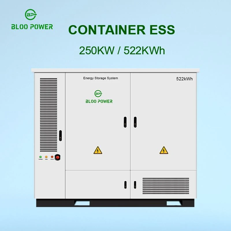
The 261kW C&I Energy Battery Storage | 125kW PCS System is a platform rather than a single model: one 261 kWh liquid-cooled enclosure that pairs with converters from 25 kW to 261 kW, parallels to ten units, and can be configured as a 1P260S string or a 2P260S dual cluster. The same 261kWh Liquid Cooled ESS Cabinet, C&I Battery Storage also ships as the 25kW/261kWh Liquid Cooling Energy Storage System for sites that need a nine-hour window, and the LFP314AH High-Capacity Energy Storage System 261 kWh cell set is common to every variant.
BP-ESS-261
125 kW / 261 kWh · 0.48C
Configuration 314 Ah · 1P260S · 832 V
DC window 679–936 V
Peak efficiency 99.0%
Cycle life >8,000 @ 80% DoD
Enclosure IP55, C3–C5 optional
Footprint 1,465 × 1,351 × 2,040 mm
BP-ESS-522
250 kW / 522 kWh · 0.48C
Configuration 314 Ah · 260S2P · 832 V
DC window 679–936 V
Peak efficiency 99.0%
Cycle life >8,000 @ 80% DoD
Enclosure IP54
Best for Single-point 500 kWh sites
125 kW / 261 kWh
0.096C · 9–10 h window
Configuration 314 Ah · 1P260S · 832 V
DC window 679–936 V
Cooling Liquid, ≤3 °C spread
Cycle life >8,000 @ 80% DoD
Best for Long arbitrage, weak-grid
support
Note Same enclosure, smaller PCS
The LFP314AH High-Capacity Energy Storage System 261 kWh against its two siblings - same chemistry, different power and paralleling architecture.
|
Parameter |
100 kWh class |
261 kWh liquid cooled |
522 kWh liquid cooled |
|
PCS rated power |
50 kW |
125 kW |
250 kW |
|
System energy |
100 kWh |
261 kWh |
522 kWh |
|
Cell / topology |
LFP |
314 Ah · 1P260S |
314 Ah · 260S2P |
|
Nominal / range DC voltage |
832 V |
832 V / 679–936 V |
832 V / 679–936 V |
|
Full-power duration (90% DoD) |
≈1.8 h |
1.88 h |
1.88 h |
|
Peak efficiency |
- |
99.0% |
99.0% |
|
Cycle life |
>6,000 |
>8,000 @ 80% DoD |
>8,000 @ 80% DoD |
|
Fire suppression |
Aerosol / FK-5-1-12 |
FK-5-1-12 + water mist |
FK-5-1-12 + water mist |
|
Operating temperature |
- |
−20 to 45 °C |
−20 to 45 °C |
Nameplate values at 25 °C unless stated. Delivered performance depends on cell batch, BMS firmware, site conditions and converter selection; the contract technical annex governs.
Where the utility mandates a specific converter certification, the BP-ESS-261 125kW 261kWh Energy Storage Cabinet is also available as a DC-only enclosure with the PCS integrated at the factory or on site. That option shifts the matching responsibility to the integrator - and makes the checks in Sections 2, 4 and 8 the integrator's job rather than the cabinet supplier's.
Conclusion: What Power Rating Should a PCS Have for a 261 kWh Energy Storage Battery Cabinet?
There is no single, universally applicable PCS power rating for a 261 kWh energy storage battery cabinet. Power ratings of 100 kW, 125 kW, 130 kW, and 150 kW can serve as starting points for evaluation. However, the final suitability depends on several factors: the battery's actual operating voltage, continuous charge/discharge current, allowable C-rate, usable State of Charge (SOC) range, and the DC input limitations of the PCS. If a project focuses primarily on long-duration load shifting, a medium-power configuration may be preferable; conversely, if high-capacity peak shaving is required, a higher-power PCS should be considered-provided that the battery system is confirmed to have the corresponding continuous output capability.
For BLOO POWER's commercial and industrial (C&I) energy storage systems, the most sound design approach is as follows: determine the target power based on load requirements; establish safety boundaries using battery parameters; verify electrical compatibility via the PCS datasheet; optimize operational performance through Energy Management System (EMS) control strategies; and finally, validate the entire system through on-site testing. This methodology helps avoid issues such as battery power limitations (caused by an oversized PCS), an inability to meet load demands (due to an undersized PCS), or incompatibilities in battery voltage or communication interfaces. Furthermore, it assists in managing both initial capital investment and long-term operational costs.
Send Inquiry