




















When Do Rack-Mounted Batteries Need to Be Connected in Parallel?
Sep 25, 2026
Leave a message

What this guide answers
- Parallel connection does one thing: it raises usable energy and continuous discharge current without changing voltage. Rack batteries get there by series-first, parallel-second - sixteen LiFePO4 cells in series make a 51.2 V module, and identical modules are then paralleled to add capacity.
- Thirteen situations force it, sorted by the resource being exhausted: capacity (five), current (three), fault tolerance and project timeline (three), and scale and physical delivery (two).
- Electrical ceiling and regulatory ceiling are different numbers. The manufacturer says how many units can be linked; the installation code says how many kilowatt-hours the location may hold. Design to the lower of the two, and expect the code to bind first.
- Most parallel failures are installation failures, not product defects: unequal cable lengths, mismatched batches, no per-string protection, and no pre-charge account for the large majority of field problems.
- Low-temperature charging is the real-world failure mode. Below 0 °C, lithium plating at the anode causes irreversible capacity loss and seeds internal short circuits. If the BMS does not block charging and no heater is fitted, one winter does measurable damage.
Why the 19-inch rack became the industry's standard building block
To answer when a rack-mounted battery parallel connection is required, it helps to understand why this particular form factor won. The 19-inch rack is a physical convention that communications and IT rooms have shared for decades: fixed internal width, vertical increments measured in rack units of 44.45 mm (1.75 in), a standard rail spacing, and established positions for panels and cable management. As storage migrated out of outdoor containers and into radio sites, hub rooms, edge locations and commercial equipment rooms, the battery had to fit infrastructure that already existed rather than the other way round.

The scale numbers explain why the segment matters. In the United States, Lawrence Berkeley National Laboratory's 2024 United States Data Center Energy Usage Report, produced for the Department of Energy, found that U.S. data centres consumed about 176 TWh in 2023, roughly 4.4% of national electricity, and projected 325–580 TWh by 2028 - between 6.7% and 12% of U.S. consumption. The IEA's Energy and AI report puts global data-centre electricity at about 415 TWh in 2024, rising to roughly 945 TWh by 2030. Behind those figures sits a power-density shift that matters more to rack-level design than the totals do: average rack density was still below 8 kW in 2024, while AI-optimised racks now draw 40–80 kW and specialised configurations move past 100 kW. Higher density per rack moves the backup problem into the rack itself.
On the telecommunications side, GSMA's regional analysis of Asia-Pacific operators recorded roughly USD 7 billion of energy spend in 2024 across some 50 TWh of electricity and 350 million litres of diesel and petrol, with renewable electricity at about 15% of consumption. Radio access networks and their supporting load are distributed, diesel-dependent and expensive to serve - which is precisely the profile that makes modular, incrementally expandable DC storage attractive. Wood Mackenzie puts 2025 global storage installations above 100 GW for the first time, about 270 GW cumulative, growing 43–51% year on year and heading toward roughly 1,545 GW by 2034, with the United States up 53% and Europe up 160% in 2025.
Underneath all of that sits one more number worth knowing if your installation is in a North American data centre: FM Global's Data Sheets 5-32 and 5-33 treat distributed lithium-ion battery-backup units above roughly 20 kWh per rack as an energy storage system, to be protected to the lithium-ion ESS data sheet. Rack-level backup and code-scoped ESS stop being separate conversations the moment a rack crosses that line.
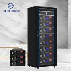
In this environment the rack format's advantages are structural. A 3U module weighs 40–65 kg (88–143 lb), so two technicians with a lift trolley can position it without rigging. Capacity is added module by module with no civil works and no need to redesign the room. One module can be taken out of service while the rest continue to carry load. BLOO POWER's BP-BSB series is built to that brief: 5 kWh, 7 kWh and 10 kWh variants sharing a 3U envelope on a 48 V / 51.2 V platform, a published maximum of 16 units in parallel, and up to 8,000 cycles at 50% depth of discharge.

The series-first, parallel-second topology. Series sets the 51.2 V platform on a 16S LFP stack; parallel connection is what actually adds stored energy and discharge current. The breakers and pre-charge resistors sitting on each string in this drawing are not decoration - they are the line between a bank that still balances in year three and one that does not.
four equations and three admission criteria
Four equations cover every situation described in the rest of this guide. Nothing below is derived from anything else.
One - capacity adds. A parallel connection leaves voltage unchanged and adds energy and current capability:
| Esystem = n × Eunit Icontinuous, system = n × Iunit |
Two - runtime. This is the step that gets over-promised, because nameplate capacity is not usable capacity:
|
T (hours) = (Enameplate × DOD × ηsystem) ÷ Pload |
DOD is taken as 0.80, the usual engineering convention for LFP. ηsystem covers internal resistance, busbar, cabling and conversion losses, and on a low-voltage rack system it typically lands between 0.90 and 0.94. At 0.92, three 10.24 kWh modules - 30.72 kWh nameplate - deliver about 22.6 kWh, roughly a quarter less than the datasheet number.
Three - circulating current. Any two parallel strings at different open-circuit voltages will drive current through each other continuously:
| Icirculating = ΔV ÷ (R1 + R2 + 2 × Rcable and busbar) |
Four - current division. Current divides between parallel strings in inverse proportion to resistance. No parameter setting changes this:
|
I1 : I2 : I3 = 1/R1 : 1/R2 : 1/R3 |
Energy scales linearly. Runtime does not.

Computed as T = Enameplate × DOD × η ÷ P, with DOD at 80% and system efficiency at 92%. The curve is steep at low load and nearly flat at high load. That shape is why "add another module" and "reduce the site load" are economically equivalent options in a surprising number of projects - and why the second one is usually cheaper.
Capacity-driven situations
Group A · the resource being exhausted is energy
01 The target backup duration exceeds what a single rack module can deliver
This is the most direct reason, and the most frequently underestimated. Take a 48 V DC site that has to hold a 2 kW critical load for eight hours. Usable energy required is 16 kWh; dividing by 80% depth of discharge and 92% system efficiency puts nameplate capacity at about 21.7 kWh. A single 10.24 kWh rack module covers roughly 3.8 hours of that, less than half the requirement. Parallel strings are not a preference here, they are the arithmetic output: you need three modules. The sequence matters more than the number. Establish the load you are protecting and the duration you are protecting it for, derive usable energy from that, and only then divide by the usable energy of one module. Working in the opposite direction - buying one unit and measuring what it covers - is how projects end up with a bank that meets the budget and not the requirement. BLOO POWER's BP-BSB series exists in three capacities on one 3U envelope precisely so that this rounding step costs as little as possible. If the calculation lands at 21.7 kWh, two 10 kWh modules fall short while three overshoot; combining a 5 kWh and a 10 kWh unit narrows the gap, provided the pair is same-model, same-batch and has comparable internal resistance, because otherwise current divides in inverse proportion to resistance and the smaller string carries a disproportionate share.
02 Site load keeps growing and a single cabinet is already near its ceiling
Communications sites almost never stay at their commissioning load. 5G and 5G-Advanced radio equipment, edge compute nodes, added CCTV and monitoring, and single-operator sites converting to shared multi-operator sites all push the -48 V DC load upward over time. Industry practice is to design for a capacity reserve of 15–25% and to size the battery bank against the load the site is expected to reach, not the load it draws on day one. When a rolling three-year plan shows a site moving from 1.5 kW to 2.8 kW, paralleling to three modules up front and leaving the free rack units for later is cheaper than installing twice and re-commissioning twice. This is where the rack format earns its place. Cabinet, busbar, protective devices, monitoring wiring, earthing and fire protection are built once; subsequent expansion is a module swap plus a busbar link plus one address registration in the monitoring interface. The BP-BSB series supports up to 16 units in parallel, and its 5, 7 and 10 kWh variants share the same 3U height, 19-inch width and 440–500 mm depth, so rail positions and busbar cut-outs set during the first installation remain valid at final capacity.
03 Off-grid and weak-grid sites must ride through consecutive overcast days or repeat outages
Off-grid solar and weak-grid sites are not designed around average irradiance; they are designed around the worst consecutive stretch. A site with a 4 kW array and 6 kWh/day consumption gets through one or two cloudy days on 15 kWh of storage. Extending autonomy to three to five days - the real requirement at many remote radio and microwave relay sites - pushes usable energy to 30–50 kWh, which means 40–65 kWh of nameplate capacity, or four to seven 10 kWh modules. There is a knock-on effect that catches people out. Once the bank grows, the charge current has to grow with it, or the array cannot refill the bank fast enough after a cloudy spell, and refill time sets the starting point of the next weather event. The GSMA figures on Asia-Pacific operator energy use illustrate the operational stakes: roughly USD 7 billion spent on energy in 2024 across 50 TWh of electricity and 350 million litres of diesel and petrol, much of it at distributed sites that are expensive to reach. BLOO POWER publishes a 100 A continuous and 200 A maximum continuous charge current for the 10.24 kWh 3U module, which is the specification that keeps recharge rate from becoming the new bottleneck once several modules are paralleled onto one array.
04 Peak shaving, demand-charge management and demand response all need throughput
Storage economics come from throughput - how many kilowatt-hours are moved per day, not how many are installed. Take commercial peak shaving with a 0.20 USD/kWh tariff spread: a 15 kWh system cycling once daily at 90% availability earns roughly 1.00 USD per day, a little over 350 USD a year. Doubling capacity roughly doubles the daily and annual revenue, while EMS, inverter, interconnection and permitting costs do not double - so payback shortens. That is the strongest economic argument for a rack-mounted battery parallel connection, and it is the one procurement teams respond to. Demand-charge management is the same logic viewed from the other side: what gets shaved is the highest 15-minute average demand, and shaving capability equals discharge power multiplied by discharge duration. Capacity that is too small cannot shave the peak at all, regardless of how well the controller works. Demand-response and virtual power plant programmes add a second threshold, because they commonly set minimum capacity and minimum dispatchable power for participation. Wood Mackenzie's finding that roughly 12% of existing U.S. systems needed capacity augmentation in 2025 in a market growing 53% year on year is a useful signal: expansion is not an edge case, it is a recognised market segment.
05 PV or wind surplus exceeds what one module can absorb
Self-consumption ratio is the metric most often miscalculated in solar-plus-storage projects. A 10 kWp array on a clear day produces 40–50 kWh; if site consumption is 20 kWh, the surplus is 20–30 kWh. One 5.12 kWh rack module typically achieves a self-consumption ratio of only 40–60%, because the battery fills early and the strongest hours around midday get curtailed. Paralleling to two or three modules lifts that to 75–85%. The important point is that the value created is not identical in kind: energy that was already generated and then curtailed is a different economic loss from energy never generated, and the same modules that capture the surplus also serve as the backup bank. Wind is the harder case, because output volatility and forecast error are both larger, and the energy buffer needed to smooth power swings is correspondingly bigger. This is where decoupling power from energy inside the same module helps. The BP-BSB-10KWH-3U gives 100 A continuous and 200 A maximum continuous discharge in a 3U envelope, so a single part number can cover short-duration high-power smoothing and long-duration low-power storage, letting the inverter scheduler decide which mode to run rather than forcing a second product into the design.
Current-driven situations
Group B · the resource being exhausted is current
06 The binding constraint is discharge current, not stored energy
This is the most common way to buy the wrong product. Suppose a site needs 6 kW of DC output capability but only 30 minutes of backup. On energy alone, 3 kWh is sufficient and a 5 kWh module looks ample. On a 51.2 V platform, however, 6 kW corresponds to roughly 117 A before conversion losses - and the continuous discharge limit of a typical 100 Ah rack module is exactly 100 A. The result is a bank that is oversized on energy and still cannot carry the load; the first transfer trips overcurrent protection. The fix is to size energy and power separately and take whichever needs more units. N+1 redundancy design starts from the same equation: divide the load current by the unit's continuous current rating to get N, then add one. One characteristic of BMS overcurrent protection deserves emphasis: it is a step function, not a gradual derating. The moment load current crosses the threshold, the entire string is disconnected in milliseconds, the remaining strings absorb the full current, and a cascade shutdown is possible. BLOO POWER's rack products separate the two current figures clearly, which is what makes this calculation possible: the 5 kWh and 7 kWh 3U modules are rated 50 A continuous and 100 A maximum continuous, the 10.24 kWh module is 100 A / 200 A, and the BP-HP rack cabinet series carries 200 A maximum continuous discharge. Size against the maximum continuous figure, not the continuous one, because backup events are precisely when load peaks.
07 Motor and inductive loads push instantaneous DC current far above nameplate
What actually trips a battery bank in the field is rarely the steady-state load. It is the first few hundred milliseconds. Motor starting current runs 3–5 times rated: a 2 kW air-conditioning compressor can present an effective 8 kW at start, and a 3 kW pump can reach four times nameplate. Referred to the 51.2 V DC side, those peaks exceed the overcurrent threshold of a single module easily. Parallel strings address this by dividing the inrush: two strings halve it per string, four strings quarter it. There is a second, subtler benefit - paralleling also slows the rate of current rise in each string, which gives BMS detection logic enough time to discriminate a genuine fault from a normal start, reducing nuisance trips. Soft starters or variable-frequency drives on the load side remain worthwhile, but they are a load-side mitigation and do not replace current headroom on the battery side. In practice this is the clearest reason to read two numbers on a datasheet rather than one: the gap between continuous and maximum continuous current is the budget available for inrush, and a selection made on the continuous figure alone will look correct on paper and fail at commissioning.
08 Conversion-side rating exceeds what the battery bank can actually deliver
System integration produces a specific and repeatable error: the inverter or PCS is selected from the load peak, the battery bank is selected from average daily consumption, and both choices are individually defensible while the combination does not work. A 10 kW hybrid inverter paired with two 5 kWh rack modules appears to have 2 × 100 A × 51.2 V, or about 10.2 kW, of discharge capability. At the bottom of the operating window near 48 V that falls to 9.6 kW, and after conversion losses it is short of the inverter's rating. The inverter at full output then holds the bank against its current ceiling, bus voltage sags, and the BMS limits output repeatedly. Leave 20–30% of headroom: a 10 kW inverter wants at least 13 kW of continuous battery discharge capability. The same asymmetry applies in -48 V telecom power systems, where the rectifier system's rated output must stay below what the battery bank can supply, because the instant mains fails the bank is asked for its maximum. The high-voltage BP-HP rack cabinet series handles this matching problem differently. Covering 256 V, 358.4 V, 512 V and 716.8 V platforms with 200 A maximum continuous discharge across the range, a single 512 V cabinet delivers around 100 kW of continuous discharge, which aligns naturally with large PCS power steps and avoids the heavy busbar and cable cross-sections that a low-voltage platform demands at the same power.
Fault tolerance and project timeline
Group C · the resource being exhausted is margin and time
09 N+1: one module must be able to fail or be serviced without dropping the site
N+1 is stated as: N is the number of modules needed to carry the critical load, and +1 is one additional module. Note what the design question actually is - can the critical load still be carried when one module is unavailable? That is a current question, not a duration question. Worked example: 6 kW critical load, about 117 A, single module rated 100 A continuous, so N = 2. Requiring the site to survive one module being withdrawn for maintenance gives N+1 = 3. In normal operation each string carries about 39 A; with one withdrawn, the remaining two carry about 59 A each, inside the 100 A limit. The condition that makes this true is reasonable current sharing. If the three strings actually divide 70 A / 35 A / 15 A, removing the string carrying 70 A produces an operating point completely unlike the design assumption. Redundancy therefore has to be verified rather than assumed: isolate one module under an approved procedure against a representative critical load, then confirm the remaining modules stay within limits and record branch current, bus voltage and temperature. The practice is established in telecom DC power design, where multi-string battery plants are configured as two or more equal-rated parallel strings with a separate disconnect device per string, so any single string can be isolated without affecting the others. BLOO POWER's CAN and RS485 master-slave architecture is what makes that verification possible; ask in procurement whether another module automatically assumes the master role, and whether the inverter degrades gracefully on loss of the communications link.
10 Budget and requirement arrive in different years, forcing staged expansion
This is the most practical reason to parallel and the one least often written into a technical document. Battery investment at large sites is usually split across budget years, while load and compliance requirements keep moving, which makes design-once, build-in-stages the default approach. The rack format only pays off if the first stage is designed for the last one: cabinet, busbar, protective devices, monitoring, earthing and fire protection are built once, and later stages add modules rather than infrastructure. That means reserving roughly 20% spare rack units and busbar taps at first installation, and selecting protective devices for final capacity rather than initial capacity, so that stage two does not require new breakers and new cable. The harder issue is electrical continuity. Staged expansion guarantees that new modules will coexist with older ones, and because current divides in inverse proportion to resistance, they will not share equally. Same model, same batch and comparable cycle count are the requirement, together with open-circuit voltage and internal resistance measurements taken before the new units are energised. The BP-BSB range's three capacities sharing one 3U envelope and 19-inch width mean rail positions and busbar positions stay valid across stages, and the published 16-unit parallel ceiling leaves enough headroom that a staged build does not run into an address-space wall halfway through.
11 An ageing bank has already drifted out of balance, and expansion must respect that
A bank that has run four or five years and accumulated thousands of cycles has higher internal resistance, lower capacity, and a settled pattern of internal current division. Adding new modules to it produces a counter-intuitive outcome. The new modules have lower resistance, so during discharge they carry far more current than their share of capacity implies and age faster; during charge they reach the voltage limit sooner, pushing the bank into constant-voltage earlier so the older modules never fully recharge. None of this is a product defect - it is resistance mismatch doing what resistance mismatch does. Engineering practice therefore sets explicit thresholds. Used-module screening typically requires an open-circuit voltage spread under 300 mV, internal resistance spread under 5% and usable energy spread under 10%, with parallel expansion of mixed-age modules generally limited to two strings above 60 V and four strings below 60 V. Beyond that, the correct architecture is separate strings under individual supervision, not a hard parallel connection. The alternative is replacement in whole, with the retired modules redeployed to non-critical or low-rate duties. BLOO POWER measures voltage and internal resistance on every module at the factory and keeps both as traceable records so that expansion projects have a baseline to compare against, and can hold same-batch stock where a project requires it.
Scale and physical delivery
Group D · the resource being exhausted is the physical limit of one unit
12 Building from 14.3 kWh rack packs to hundreds of kWh and megawatt-scale containers
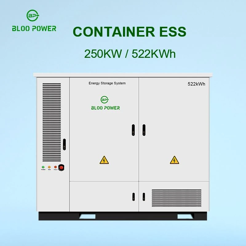
Once a project moves from an equipment room to a container or prefabricated enclosure, the rack battery changes role: it stops being a finished product and becomes a standard component of a larger system. The reason is simple. There is a physical ceiling on what one unit can be, and no ceiling on system capacity requirements. Transport, lifting, fire compartmentation and site access all constrain the size and mass of any single battery cabinet, so splitting capacity into uniform rack modules lets module production and testing happen in a factory while final assembly happens on site - and lets one large investment become a sequence of smaller ones. BLOO POWER's published examples illustrate both ends of this. The 500 kWh containerised system is built from 35 rack battery packs of 14.3 kWh each, supervised by a high-voltage controller that monitors and balances the whole bank, with CAN, RS232 and RS485 interfaces and the ability to accept PV, diesel generator and grid inputs at megawatt scale. The high-voltage rack cabinet series takes the other route, presenting itself as a finished unit: the BP-HP-150KWH is a 512 V / 300 Ah configuration rated 153.6 kWh over a 400–574 V window, which supports roughly a hundred kilowatts on the AC side from a single cabinet. Thirty-five paralleled and series-combined 14.3 kWh packs are the same engineering manoeuvre as a three-module rack bank, executed three orders of magnitude larger.
13 Delivery and site access: module weight decides whether the project is buildable
The last situation is invisible on a drawing and decisive on site. A monolithic 10 kWh battery cabinet weighs 100–165 kg. Getting it from the loading dock to the equipment room may involve a goods lift, a corridor, a door frame and two turns, and if any of those is too narrow or the floor slab is not rated for the point load, the design changes. A 40–65 kg 3U module, by contrast, can be moved and racked by two people with a trolley, assembled on arrival, and installed without rigging equipment - which lowers both cost and site risk. The same asymmetry applies to maintenance. A failure in a monolithic cabinet tends to mean the whole unit comes out of service and goes back to the factory, whereas a rack module is swapped on site while the rest of the bank keeps carrying load. BLOO POWER's design choices reflect this directly: 3U modules measuring 440 × 400 × 130 mm to 500 × 442 × 130 mm at 40–65 kg, a wheeled cabinet range (BP-HP-20/40/60/80KWH on a 51.2 V platform) for projects that need the bank moved as a unit, and the high-voltage rack cabinet series for projects that need a higher voltage platform. Write the site constraints into the specification - corridor width, lift capacity, floor loading, ceiling height - and let them choose between modules and cabinets, rather than discovering the answer at delivery.
What paralleling costs: circulating current, mismatch, and the code ceiling
A parallel connection is not free. It carries three costs, none of which appear in a factory test report, and most of which surface twelve to twenty-four months later as one string that measures weaker than its neighbours.
The first cost is steady-state circulating current. Any two parallel strings at different open-circuit voltages will charge each other continuously, whether or not the system is serving load. On a 51.2 V platform, one string at 85% state of charge sits near 54.4 V and another at 72% near 52.8 V - a 1.6 V difference. Divide that by a combined loop resistance of about 50 milliohms and the standing current is roughly 32 A; reduce the loop resistance to 25 milliohms through shorter runs and larger cross-sections and the same voltage difference drives about 64 A. That current does no useful work at all. It becomes heat, it runs continuously, it pulls both strings further out of balance, and it can trigger protective shutdowns on both BMS units at once. IEC 62619 treats uniform current sharing as a design condition for parallel configurations rather than an optional refinement, and its 2022 edition tightened BMS functional safety to require disconnection within 200 ms of an abnormal condition followed by a fail-safe state that prevents automatic restart.
Standing current runs whether or not the site is drawing load

Computed as I = ΔV ÷ R, where R is the total loop resistance of both strings plus cable and busbar. The slope carries a counter-intuitive message: shorter runs and larger conductor cross-sections make circulating current worse, not better. The answer is not to add resistance, it is to bring the pre-connection voltage difference inside 0.05 V and to remove resistance differences between strings through equal-length routing.
The second cost is impedance mismatch in cables and busbars. Current divides in inverse proportion to resistance, and resistance includes the cable. If the string nearest the busbar has a 1.2 m run and the far string has 2.4 m of the same cross-section, the far string carries less and the near string carries more, discharges deeper and ages faster. Nothing on the drawing reveals this, because both cables carry the same part number. The remedy is procedural: if one run is 1.2 m, every run is 1.2 m, with excess coiled and cable-tied rather than cut short; and terminations are taken diagonally, positive from the first unit and negative from the last, so that path resistance is as close to identical as the layout allows.
The third cost is the code ceiling, and the 2026 edition of NFPA 855 is a material change. The 2023 edition allowed designers to avoid a hazard mitigation analysis where an installation fell into one of several pre-defined exempt configurations. The 2026 edition removes those off-ramps: an HMA covering thermal runaway propagation, gas accumulation, fire propagation paths and emergency response is now the default requirement for virtually all ESS installations. Section 9.7.6.6 is new and requires thermal runaway propagation prevention systems engineered to NFPA 69 rather than standalone deflagration venting. A minimum three-foot (0.9 m) separation now applies between lithium-ion battery groups above 50 kWh, reducible only where UL 9540A data or large-scale fire test results demonstrate no propagation at the smaller distance. Any indoor commercial installation above 600 kWh must occupy a dedicated battery room with explosion venting, emergency power-off circuits, fire-rated construction and segregation from occupied space. Individual units or cabinets are capped at 50 kWh on the prescriptive path without large-scale fire test relief, and the lithium-ion ESS trigger sits at 20 kWh of aggregate stored energy.
Those numbers interact with rack sizing in a way that is worth stating plainly. Working in 10.24 kWh modules, a prescriptive 50 kWh per-cabinet cap is reached at five modules. The 16-unit electrical ceiling published for the BP-BSB series corresponds to about 163.8 kWh, which is well inside a 600 kWh per-fire-area allowance but outside the 50 kWh cabinet allowance unless large-scale fire test data applies. The practical consequence is that a rack-mounted battery parallel connection in the United States is usually limited by the code path a project can qualify for, not by what the BMS can address. Confirm which edition your authority having jurisdiction has adopted before designing to it - adoption typically lags publication by two to four years, so both the 2024 and 2026 cycles are in force somewhere, and the 2026 edition's alignment with UL 9540A 6th Edition, which added installation-level large-scale fire testing, changes what evidence a submittal package needs.
Low-temperature charging: the failure point that sits outside the datasheet headline
Almost every rack-mounted LFP product lists two temperature windows, and they are not the same window. BLOO POWER's rack products discharge from −20 °C to 65 °C (−4 to 149 °F), with the high-voltage cabinet range discharging from −10 °C to 55 °C (14 to 131 °F), while the charging lower limit is normally 0 °C (32 °F). The reason is that charging below freezing plates metallic lithium on the anode, causing irreversible capacity loss and seeding the internal short circuits that later become thermal events. In unheated equipment rooms, outdoor integrated cabinets, and remote sites with large diurnal swings, this is a genuine operational risk rather than a theoretical one. If a project must charge at low temperature, confirm that the BMS blocks charging below the threshold and specify heating film or a heated enclosure - do not rely on the assumption that a lower charge current makes it safe.
published rack-mounted battery parallel connection capability
Put the two curves on one chart and the distinction becomes obvious: capacity rises linearly with unit count, while the permitted capacity in a given location is a horizontal line that does not move.
Capability scales linearly. Permission does not.

Dark blue is the 10.24 kWh module, lighter blue the 5.12 kWh module. The two dashed horizontal lines do not move with unit count. Five 10.24 kWh modules reach 51.2 kWh and cross the 50 kWh prescriptive per-cabinet cap; the 16-unit electrical ceiling corresponds to 163.8 kWh. The design consequence is that in most North American projects the BMS ceiling is not the binding constraint - the code path is.
Published parallel capability of the BLOO POWER rack battery range (from manufacturer product data)
The high-voltage cabinets (BP-HP-50/100/150/200KWH) ship as complete units; expansion happens through cabinet-to-cabinet paralleling and series stacking. Final parallel unit counts for any project must be confirmed in writing by the manufacturer.
|
Series / model |
Energy per unit |
Nominal voltage |
Continuous / max continuous discharge |
Published parallel capability |
System capacity at ceiling |
|
BP-BSB-5KWH-3U (low-voltage 3U) |
5 kWh (100 Ah) |
48 / 51.2 V |
50 A / 100 A |
Up to 16 units in parallel |
~81.9 kWh |
|
BP-BSB-7KWH-3U (low-voltage 3U) |
7 kWh (150 Ah) |
48 / 51.2 V |
50 A / 100 A |
Up to 16 units in parallel |
~110.6 kWh |
|
BP-BSB-10KWH-3U (low-voltage 3U) |
10 kWh (200 Ah; ~10.24 kWh nameplate) |
48 / 51.2 V |
100 A / 200 A |
Up to 16 units in parallel |
~163.8 kWh |
|
BP-HP-20KWH (wheeled LV cabinet) |
20 kWh (400 Ah) |
51.2 V |
- / 200 A |
Published example: 6 units in parallel forming 90 kWh |
≥ 90 kWh (6 units) |
|
BP-HP-40 / 60 / 80KWH (wheeled LV cabinet) |
40 / 60 / 80 kWh (800 / 1120 / 1600 Ah) |
51.2 V |
- / 200 A (160 A max continuous charge) |
Expands on the same cabinet-to-cabinet logic |
per bank |
|
BP-HP-50KWH (HV rack cabinet) |
51.2 kWh (200 Ah) |
256 V (200–292 V) |
- / 200 A |
Cabinet-to-cabinet parallel / series stacking |
51.2 kWh per unit |
|
BP-HP-100KWH (HV rack cabinet) |
100.3 kWh (280 Ah) |
358.4 V (280–408.8 V) |
- / 200 A |
Cabinet-to-cabinet parallel / series stacking |
100.3 kWh per unit |
|
BP-HP-150KWH (HV rack cabinet) |
153.6 kWh (300 Ah) |
512 V (400–574 V) |
- / 200 A |
Cabinet-to-cabinet parallel / series stacking |
153.6 kWh per unit |
|
BP-HP-200KWH (HV rack cabinet) |
200.7 kWh (280 Ah) |
716.8 V (627.2–817.6 V) |
- / 200 A |
Cabinet-to-cabinet parallel / series stacking |
200.7 kWh per unit |
|
500 kWh containerised ESS |
35 × 14.3 kWh rack packs + HV controller |
HV platform |
scheduled by the HV controller |
Modular combination, extensible to MW-scale microgrids |
from 500 kWh |
On cycle life, two published figures disagree and the difference matters. The BLOO POWER BP-BSB series pages list ≥2,000 cycles at 100% depth of discharge, ≥4,000 at 80% DOD and ≥8,000 at 50% DOD, while the third-party datasheet indexed on ENF Solar for the BP-BSB-5KWH states 6,500 cycles at 80% DOD with a 15-year design life. The BP-HP cabinet series is published at 6,500 cycles at 80% DOD. Divergence of this kind normally traces to test conditions - discharge rate, ambient temperature, cut-off voltage, and whether end of life is defined at 70% or 80% of initial capacity. A specification should require the test conditions to be written into the technical agreement rather than accepting a standalone number.
On certification, separate what a vendor holds from what a project must request. BLOO POWER's published material lists UN38.3, MSDS, CE, FCC and RoHS for its rack products. UL 1973, UL 9540 / 9540A and IEC 62619 sit at module, system and installation level respectively, and should be requested per project regardless of vendor. Check the scope of any UL 9540 listing as well: the certification covers the system as installed, so a listing tested with two units in parallel does not automatically extend to three.
what each market actually permits
Capacity limits are jurisdictional, and they are the constraint most often discovered late in a project. The frameworks below determine how much storage a location may hold, which in turn determines the maximum sensible unit count regardless of what the datasheet allows.
Parallel expansion is constrained by regulation; these frameworks answer "how much may this location hold" rather than "can this product be paralleled"
|
Market |
Governing documents |
Capacity and siting limits |
What it means for unit count |
|
United States |
NFPA 855 (2026), UL 9540 / UL 9540A, NEC Article 706, IFC 1207, IRC R328, FM Global DS 5-32 / 5-33 |
Lithium-ion ESS trigger at 20 kWh aggregate. Individual unit or cabinet capped at 50 kWh on the prescriptive path. 3 ft (0.9 m) minimum separation between lithium-ion groups above 50 kWh, reducible only with UL 9540A data. 600 kWh maximum per fire area in an occupied building; above that, a dedicated battery room with explosion venting and emergency power-off. HMA now required by default. Two-hour fire separation from other occupancies. |
Five 10.24 kWh modules reach 51.2 kWh and cross the 50 kWh cabinet cap. A 600 kWh fire-area allowance is not the binding limit - the 16-unit electrical ceiling is lower. In data centres, FM Global treats distributed lithium-ion backup above roughly 20 kWh per rack as an ESS, so rack-level UPS lines fall inside the scope rather than outside it. |
|
United Kingdom |
BS 7671:2018+A4:2026 Chapter 57, PAS 63100:2024, MCS MIS 3012, IET Code of Practice (3rd ed.), ENA G98 / G99 |
No single kWh cap; the constraint is siting. Excluded from sleeping rooms, lofts and protected escape routes. External units need roughly 1 m clearance from windows, doors and vents. G98 covers up to 3.68 kW per phase; anything above goes through G99. |
Expansion is governed by location rather than by a number. Alterations carried out after 15 October 2026 must satisfy the current rules, so adding modules to a loft installation may force relocation first. |
|
European Union |
IEC 62619, IEC 63056, IEC 62109; national overlays including VDE-AR-E 2510-50 (Germany); EU Battery Regulation (EU) 2023/1542 |
Product-level safety is harmonised through the IEC framework; siting is set nationally. German projects commonly require a VDE-AR-E 2510-50 declaration of conformity. |
IEC 62619 makes uniform current sharing a design condition for parallel configurations rather than an optional refinement. National overlays must be verified market by market. |
|
Australia / New Zealand |
AS/NZS 5139:2019+A1, AS/NZS 3001.2:2022 |
Applies to 12–1500 V DC and units from 1 to 200 kWh. Lithium cells are classified as fire hazard Level 1. Not permitted in habitable rooms; at least 600 mm from exits and 1 m of clear access in front. |
Multiple systems are assessed individually, and the standard explicitly prevents splitting capacity to stay under a threshold. Two 40 kWh systems are not equivalent to one 80 kWh system for compliance purposes. |
|
China |
GB/T 36276-2023, GB 44240-2024 |
Recommendatory rather than mandatory in law, but routinely invoked as a binding technical condition in tenders. Cell capacity deviation ≤3%, internal resistance deviation ≤20%, and at least 80% capacity retention after 5,000 cycles. The 2023 revision added a thermal runaway propagation suppression test. |
Directly constrains the cell consistency of multi-unit assemblies. When consistency is out of specification, parallel behaviour amplifies the imbalance rather than averaging it out. |
Codes are revised continuously and local authorities frequently add requirements of their own. Both the 2024 and 2026 NFPA 855 cycles are in force in different jurisdictions, and the 2026 edition changes both the analysis requirements and the evidence a submittal needs. Treat this table as a scoping aid and confirm against the edition your authority having jurisdiction has actually adopted.
Three cases where paralleling is the wrong answer
A guide that only explains when to parallel should not be trusted. In three situations the correct decision is not to.
When the modules do not match
A wide cell voltage spread, high internal resistance dispersion or a large cycle-count difference should not be hard-paralleled. Current divides in inverse proportion to resistance, so dispersion means one string runs persistently overloaded and the other persistently underloaded, and both retire early. Use separate strings under a supervisory controller, which absorbs the variation in the control layer instead of amplifying it in the physical layer.
When the code ceiling has been reached
Once the location's permitted capacity is used up, adding another string addresses the wrong constraint. Change the installation location, or select a product with installation-level large-scale fire test data to support a reduced separation distance. Both are legitimate engineering answers; neither is a wiring change. Most retrofits of this kind are avoidable by calculating final unit count and permitted site capacity in the same exercise at concept stage.
When capacity is already sufficient
Adding modules lengthens payback, raises floor loading and adds heat to the room. Storage revenue comes from cycles actually delivered, not from nameplate kilowatt-hours. Before that final number goes into the purchase order, ask how many times a year the extra capacity will complete a full cycle. If the answer is "rarely", the question is not whether to parallel - it is whether the system is over-provisioned.
Eight clauses to put in your specification
The clauses below can be pasted into a technical specification as written. Their purpose is to convert "parallel connection" from an installation activity into a set of verifiable acceptance criteria.
State the protected load and the protected duration. Require the bidder to present a critical load schedule, the power of each load, and the target backup duration as a single package before deriving usable energy and unit count. A unit count submitted on its own is not a design.
01
State the parallel unit ceiling explicitly, with written manufacturer confirmation. For reference, BLOO POWER publishes a 16-unit maximum for the BP-BSB low-voltage 3U series. Any configuration beyond a published figure requires written confirmation, because exceeding the BMS address space breaks both SOC reporting and master-slave heartbeat.
02
Require identical model and batch, with numeric dispersion limits. Suggested values: open-circuit voltage spread ≤300 mV, internal resistance spread ≤5%, usable energy spread ≤10%. For staged expansion, require the manufacturer to hold same-batch stock or to supply factory test records that allow comparison.
03
Require independent overcurrent protection and a DC-rated disconnecting means per string. This corresponds to NEC 706.31 for string overcurrent protection and NEC 706.15 for a disconnecting means capable of isolating all ungrounded conductors. AC-rated devices are not a substitute: DC fault current has no natural zero crossing to assist interruption.
04
Require per-string pre-charge, and put the admission logic inside the BMS. Specify a voltage difference ≤0.05 V (≤0.02 V in critical applications), SOC difference ≤5% and temperature difference ≤5 °C as conditions for closing; pre-charge resistor 50–100 Ω at ≥50 W; and an interlock that prevents main contactor closure before pre-charge completes.
05
Require a master-slave architecture, with a defined degradation strategy. One master BMS publishes voltage, state of charge and available power. Specify what happens on heartbeat loss, whether a new master is elected automatically, and whether the inverter can continue in a degraded mode without the communications link.
06
Require certification evidence at the correct level, and verify the scope. Request UL 1973 or IEC 62619 at cell and module level, UL 9540 / 9540A at system and fire level where applicable, and UN 38.3 for transport. Verify that the certificate covers the actual parallel unit count and the actual inverter model, since a system-level listing is configuration-specific.
07
Require explicit low-temperature charging behaviour. Specify the BMS charge temperature lower limit (commonly 0 °C / 32 °F), the action taken when it is reached, and whether heating film or a heated enclosure is included. In cold-climate sites this is the most common real failure mode and belongs in the technical conditions, not in a notes section.
08
Parallel admission criteria and field verification - designed to be used directly as a commissioning record header
|
Criterion |
Typical requirement |
Why it is the criterion |
How to verify on site |
|
String open-circuit voltage difference |
≤0.05 V (≤0.02 V critical) |
Circulating current is proportional to voltage difference; 0.1 V across a 50 mΩ loop is about 2 A of continuous standing current |
Measure and log each string with a digital multimeter before paralleling; read both ends of each string |
|
String SOC difference |
≤5% (3% preferred) |
SOC spread maps to open-circuit voltage spread on an LFP platform and is the root cause of circulating current |
Read reported values over CAN or RS485 and cross-check against measured string voltage |
|
Module-to-module temperature difference |
≤5 °C (9 °F) |
Temperature changes internal resistance and usable capacity, which changes current division between strings |
Log module surface and terminal temperature at top, middle and bottom of the cabinet |
|
Insulation resistance |
≥100 MΩ (HV systems) |
Falling DC insulation resistance is the precursor to arcing and shock risk |
Test only by the manufacturer-approved method; routine megohmmeters can damage BMS semiconductors and read filter capacitance as leakage |
|
Equal-length, equal-section cabling |
Same cross-section; length deviation <5% |
String current is inversely proportional to loop resistance, so doubling run length shifts current away from one string and toward another |
Measure and record every positive and negative cable run; take positive from the first unit and negative from the last |
|
Per-string overcurrent protection |
Independent breaker or fuse per string, DC-rated |
A fault should isolate one string rather than take the bank offline; also required by NEC 706.31 |
Verify DC rating and interrupting capacity on the nameplate, and confirm protection coordination (string, then group, then main) |
|
Pre-charge circuit |
50–100 Ω, ≥50 W, per string |
Inrush at closure is set by voltage difference and loop resistance; direct closure pits contacts and welds contactors |
Record peak current at closure with a clamp meter or oscilloscope; confirm no abnormal surge |
|
Master-slave communications |
CAN or RS485, single master publishing externally |
Independent SOC decisions cause staggered protection trips, overloading remaining strings and cascading |
Interrupt one communications path and confirm the system degrades as designed rather than shutting down |
|
Measured current sharing |
Branch current deviation ≤10% at rated load |
N+1 redundancy depends entirely on reasonable current sharing; without it the redundancy does not exist |
Run at full load for 30 minutes and log each branch with a clamp meter against the design value |
|
Low-temperature charge blocking |
Charging inhibited below 0 °C, or heating energised first |
Charging below freezing causes lithium plating: irreversible capacity loss and the origin of later internal short circuits |
Issue a charge command under low-temperature conditions and confirm the BMS rejects it or heats before charging |
The BLOO POWER rack battery line
Low-voltage 3U modules
BP-BSB series 3U rack-mounted batteries
Three capacities on one 3U envelope and one 19-inch width, on 48 V and 51.2 V platforms, with a published maximum of 16 units in parallel. An integrated BMS with SNMP support makes the series the basic expandable unit for radio sites, hub rooms and edge locations.
- 440 × 400 × 130 mm to 500 × 442 × 130 mm (3U); 40–65 kg / 88–143 lb
- 50–100 A continuous, 100–200 A maximum continuous charge and discharge
- RS485 / CAN with RS232 on some models; compatible with mainstream off-grid and hybrid inverters
- Up to 8,000 cycles at 50% depth of discharge; 10-year warranty
High-voltage rack cabinets
BP-HP high-voltage rack battery cabinets (50–200 kWh)
Four voltage platforms - 256 V, 358.4 V, 512 V and 716.8 V - with 51.2 to 200.7 kWh per cabinet and 200 A maximum continuous discharge. These connect directly to PCS and high-voltage hybrid inverters for commercial peak shaving and demand-charge management, where revenue is metered in kilowatt-hours.
- 512 V platform: 153.6 kWh per cabinet (300 Ah, 400–574 V)
- 8,000 cycles at 80% DOD; charge 0–55 °C, discharge −10–55 °C
- RS485 / CAN / RS232; compatible with mainstream off-grid and hybrid inverters
- 3U or 4U customisation; racked, cabinet-mounted or stacked
Containerised systems
500 kWh modular rack-pack energy storage system
Built from 35 rack battery packs of 14.3 kWh each under a single high-voltage controller that monitors and balances the whole bank. CAN, RS232 and RS485 interfaces accept PV, diesel generator and grid inputs, making it the megawatt-scale expression of the same parallel-connection principle.
- 35 × 14.3 kWh rack packs plus HV controller architecture
- Unified monitoring and balancing, extensible to MW-scale microgrids
- Suited to peak shifting, backup and off-grid operation
- Module-level transport and on-site assembly reduce rigging and access requirements
Send Inquiry