





















261kWh Energy Storage Cabinet: How Far Can Parallel Expansion Scale in MWh?
Oct 20, 2026
Leave a message

A 261kWh energy storage cabinet can serve as a modular building block for commercial and industrial battery energy storage systems (BESS), with theoretical battery capacity scaling to 1MWh, 2MWh, 5MWh, 10MWh, and beyond. The actual expansion limit, however, depends on more than the number of cabinets installed. Power conversion system (PCS) ratings, DC and AC distribution architecture, battery management, energy management controls, transformer capacity, fire protection, and grid interconnection requirements all influence the maximum practical system size.
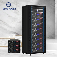
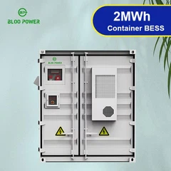
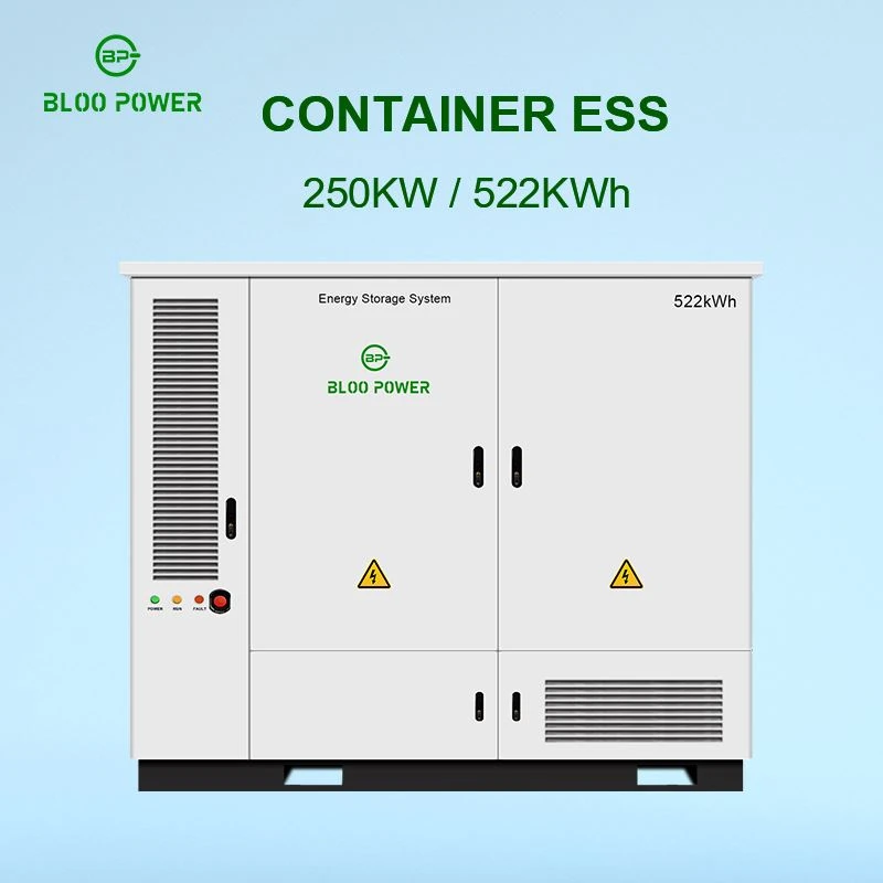
For commercial and industrial users, modular expansion offers a way to align capital expenditure with actual energy demand. A facility can initially install a smaller storage system and add capacity as electricity consumption grows, photovoltaic generation increases, or peak-demand management requirements change. BLOO POWER's published 261kWh liquid-cooled energy storage cabinet is one example of a standardized storage unit designed for commercial and industrial applications. Its published configuration includes 261kWh of battery capacity and a 125kW PCS rating, providing a useful reference for preliminary system calculations.
The key distinction is between theoretical battery energy and a fully engineered, operational BESS. While cabinet arithmetic can establish a nominal MWh target, only a verified electrical design can determine whether a particular number of cabinets can operate together safely, reliably, and in compliance with local requirements.

Understanding the Expansion Potential of a 261kWh Energy Storage Cabinet
A 261kWh energy storage cabinet integrates battery cells, battery modules, a battery management system (BMS), thermal management, electrical protection, and other components required by its specific design. Depending on the product architecture, the cabinet may also incorporate a PCS and system-level controls. This integration allows project developers to plan storage capacity in standardized increments instead of designing every battery installation from individual cells or modules.
For a BLOO POWER 261kWh liquid-cooled cabinet, the published product configuration specifies LiFePO4 battery technology, a nominal DC voltage of 832V, a 125kW PCS rating, and an operating voltage range of 679–936V. These parameters help establish an initial engineering reference, although the final equipment configuration must be confirmed against the applicable product datasheet and project technical agreement.
The nominal energy calculation is straightforward:
Total nominal battery energy = Number of cabinets × 261kWh
Four cabinets provide 1,044kWh, or 1.044MWh. Twenty cabinets provide 5,220kWh, or 5.22MWh. Forty cabinets provide 10,440kWh, or 10.44MWh.
These figures describe the arithmetic sum of the stated cabinet capacities. They do not establish usable AC energy, maximum discharge power, guaranteed operating duration, or the manufacturer's permitted parallel configuration. Those parameters require separate verification.
For commercial energy storage projects, this distinction is important because energy capacity and power capacity serve different functions. A large battery bank may support longer discharge periods, while PCS capacity determines how quickly that stored energy can be delivered. Effective BESS expansion therefore requires coordinated planning of both the battery side and the power conversion side.
How Many 261kWh Cabinets Are Required for 1MWh, 5MWh, or 10MWh?
The required number of cabinets depends on the target nominal energy capacity. Since a cabinet provides 261kWh, the initial cabinet count can be calculated by dividing the target energy in kilowatt-hours by 261 and rounding up to the next whole cabinet.
The formula is:
Required cabinet count = Ceiling (Target energy in kWh ÷ 261kWh)
For example, a 5MWh target equals 5,000kWh. Dividing 5,000 by 261 gives approximately 19.16, so at least 20 cabinets are required to exceed that nominal capacity. Their combined capacity is 5.22MWh.
Cabinet quantity and nominal energy reference
|
Target nominal capacity |
Cabinet quantity |
Combined nominal energy |
Excess above target |
|
Approximately 1MWh |
4 |
1.044MWh |
44kWh |
|
Approximately 2MWh |
8 |
2.088MWh |
88kWh |
|
Approximately 3MWh |
12 |
3.132MWh |
132kWh |
|
Approximately 5MWh |
20 |
5.220MWh |
220kWh |
|
Approximately 8MWh |
31 |
8.091MWh |
91kWh |
|
Approximately 10MWh |
39 |
10.179MWh |
179kWh |
|
Approximately 20MWh |
77 |
20.097MWh |
97kWh |
Calculation basis: 261kWh per cabinet, with the cabinet quantity rounded up. The table does not certify that every listed configuration is supported by a particular manufacturer.
This method is useful for early-stage project sizing, budgeting, and site planning. However, a project targeting 5MWh of usable AC energy may require more than 20 cabinets if the system has restricted operating SOC limits, conversion losses, auxiliary consumption, or an end-of-life energy guarantee.
BESS developers should therefore define whether the project requirement refers to nominal battery energy, usable DC energy, usable AC energy at the PCS output, or guaranteed energy delivered at the point of interconnection. These definitions can lead to different equipment quantities and contractual performance requirements.
Why MWh and MW Must Be Designed Separately
Energy capacity, measured in kilowatt-hours or megawatt-hours, describes how much energy a battery can store. Power capacity, measured in kilowatts or megawatts, describes how quickly the system can charge or discharge. A 5.22MWh battery system with a 2.5MW PCS has a different operating profile from the same battery system with a 1MW PCS.
A simplified theoretical duration calculation is:
Nominal duration (hours) = Nominal battery energy (MWh) ÷ Rated discharge power (MW)
For a 5.22MWh system operating at 2.5MW, the ratio is approximately 2.09 hours. At 1MW, the ratio becomes 5.22 hours. These are nominal energy-to-power ratios, not guarantees of actual discharge duration.
Real-world duration depends on the permitted SOC window, battery temperature, power limits, PCS efficiency, auxiliary loads, degradation, and operating conditions. If a facility requires 4MWh of AC energy over a four-hour peak period, a 5.22MWh nominal battery may or may not satisfy the requirement. The design must establish how much energy is available at the required discharge rate and at the specified point of measurement.
The US National Renewable Energy Laboratory's Annual Technology Baseline treats battery energy-to-power ratio as a key parameter in commercial battery storage modeling and evaluates systems across different storage durations. This supports a fundamental engineering principle: BESS sizing should begin with the application's required power and duration rather than a nominal MWh target alone.
PCS Sizing for a Multi-Cabinet BESS
he power conversion system is one of the primary factors governing practical expansion. Increasing battery capacity does not automatically increase AC output power. If additional cabinets are connected to a system whose PCS capacity remains unchanged, the installation may store more energy while retaining approximately the same maximum conversion power, subject to the approved configuration.
BLOO POWER publishes a 261kWh cabinet configuration with a 125kW PCS rating. For preliminary calculations, this corresponds to an approximate rated power-to-energy ratio of 0.48C:
125kW ÷ 261kWh ≈ 0.48h⁻¹.
This ratio describes the relationship between the PCS rating and nominal cabinet energy. It should not be interpreted as the maximum electrochemical charge or discharge rate of the battery cells.
If a project uses 20 complete 261kWh/125kW units and the manufacturer confirms that all units can operate together in the proposed configuration, the arithmetic totals would be 5.22MWh and 2.5MW. However, this calculation is valid only if each unit includes the relevant power conversion equipment and the combined system is supported by the approved architecture.
A centralized PCS design may connect multiple battery cabinets to shared conversion equipment. A distributed design may use separate PCS units for individual cabinets or groups of cabinets. These approaches have different requirements for DC protection, communications, fault isolation, power sharing, and maintenance.
The correct PCS rating should be based on the required peak-demand reduction, charging power, grid connection limit, and desired discharge duration. Oversizing the PCS without a corresponding operational benefit can increase capital costs, while undersizing it may prevent the battery from delivering the required power.
Example Configurations for 1MWh, 2MWh, 5MWh, and 10MWh Systems
The following table illustrates how cabinet quantity and assumed PCS power can scale together when every cabinet is treated as a complete 261kWh/125kW unit. It is a calculation example, not a statement that every system size is covered by a single approved product configuration.
|
Cabinet quantity |
Nominal battery energy |
Assumed aggregate PCS rating |
Nominal energy-to-power ratio |
|
4 |
1.044MWh |
0.5MW |
2.09h |
|
8 |
2.088MWh |
1.0MW |
2.09h |
|
20 |
5.220MWh |
2.5MW |
2.09h |
|
40 |
10.440MWh |
5.0MW |
2.09h |
This comparison assumes that the rated PCS power of each cabinet can be aggregated without derating or other restrictions. Actual projects may use different PCS arrangements, and aggregate output may be limited by transformer capacity, grid export limits, ambient conditions, control settings, or equipment ratings.
For a 10MWh-class installation, 39 cabinets would provide 10.179MWh of nominal battery energy. If each cabinet were configured with a 125kW PCS, the arithmetic sum would be 4.875MW of rated conversion power. Whether that power can be delivered simultaneously depends on the system architecture and the electrical limits of the complete installation.
A practical design should also consider whether the project needs a two-hour, four-hour, or longer-duration discharge profile. A system with a higher energy-to-power ratio may require fewer megawatts of PCS capacity relative to its MWh rating, whereas applications requiring short-duration, high-power delivery may need a different configuration.
Centralized PCS vs. Distributed PCS Architecture
Centralized PCS architecture connects multiple battery cabinets through a designed DC collection system to one or more larger power conversion units. This approach can simplify the organization of conversion equipment, but it requires careful engineering of DC busbars, protection devices, cable sizing, fault isolation, and battery-string coordination.
Distributed PCS architecture assigns separate conversion equipment to individual battery units or smaller groups. It can support modular commissioning and localized maintenance, provided that the equipment is designed for the intended parallel operation. However, it may involve more individual power conversion units, communication links, and control interfaces.
Neither architecture is universally superior. Selection depends on the required system scale, redundancy strategy, installation constraints, maintenance resources, efficiency profile, and the manufacturer's validated design.
For BLOO POWER 261kWh BESS projects, the project team should establish whether the cabinet is supplied with an integrated PCS, whether the PCS can operate in parallel with other units, and how the manufacturer defines the supported expansion boundary. The engineering documents should also identify whether battery cabinets may share a common DC bus and what protection arrangements are mandatory.
For staged expansion from approximately 1MWh to 5MWh, it is worth evaluating the final system architecture before the first phase is installed. Planning for future capacity can reduce the risk of replacing distribution equipment, communication hardware, or transformers later. Nevertheless, equipment should not be oversized without a clear technical and commercial justification.
DC Busbars, AC Distribution, and Transformer Capacity
As cabinet quantity increases, the electrical design must account for aggregate current, fault current, cable routing, voltage drop, thermal limits, and protective-device coordination. For a shared DC architecture, busbars, fuses, contactors, cables, and isolation devices must be rated for the actual operating voltage and current. For an AC-coupled system, the design must also account for PCS output current, switchgear ratings, busbar temperature rise, fault withstand capability, power quality, and transformer loading.
The nominal capacity of a battery bank does not establish the available grid connection capacity. For example, a 5.22MWh system with 2.5MW of PCS capacity cannot necessarily charge or discharge at 2.5MW if the site's transformer is already heavily loaded or the utility imposes a lower import or export limit.
Transformer sizing must reflect the expected bidirectional power flow, site load profile, power factor, voltage level, ambient conditions, and relevant operating margins. A peak-shaving application may need EMS controls to restrict charging during high site demand, while a photovoltaic-plus-storage installation may require export limitation to comply with the interconnection agreement.
The electrical design should be completed by qualified engineers familiar with the applicable standards and grid requirements. Short-circuit studies, grounding design, protection coordination, metering, anti-islanding functions, and grid-support settings should be reviewed before commissioning. These requirements become increasingly important as the project moves from a small commercial installation toward a multi-megawatt BESS.
BMS, EMS, and Multi-Cabinet Communication
The battery management system monitors battery operating conditions and enforces battery-level protection limits. Depending on the system design, it may monitor cell or module voltage, current, temperature, SOC, insulation status, and fault conditions. The energy management system coordinates the wider installation by managing dispatch schedules, charging and discharging power, grid import and export, and operating priorities.
In a multi-cabinet BESS, reliable communication is essential. Each cabinet must communicate correctly with the relevant controller, while the EMS may also need data from the PCS, meters, transformers, photovoltaic equipment, and site energy management platform. Communication compatibility involves more than having the same physical interface: CAN, RS485, Ethernet, and Modbus implementations may differ in data mapping, command behavior, firmware versions, and control logic.
For larger BLOO POWER installations, the commissioning plan should define communication addressing, device discovery, alarm mapping, response to communication loss, and the behavior of the system when one cabinet is unavailable. The control strategy should also address SOC imbalance and uneven power sharing among cabinets.
If a cabinet reaches a temperature limit or reports a battery fault, the system should respond according to the manufacturer's approved protection logic. It should not assume that all other cabinets can continue operating without restriction. Similarly, adding new cabinets to an existing BESS may require firmware compatibility checks, revised EMS configuration, updated power limits, and commissioning tests.
A robust control architecture allows modular capacity to be coordinated without sacrificing protection or operational visibility.
Liquid Cooling and Thermal Management at MWh Scale
Liquid cooling can help maintain battery operating temperatures and reduce temperature differences among cells. This is important because temperature affects internal resistance, charging acceptance, available power, aging, and safety. However, installing more cabinets increases the total thermal management demand and can create new site-level constraints.
BLOO POWER's published 261kWh liquid-cooled cabinet specifies a cell-to-cell temperature differential typically of no more than 3°C under its stated conditions. The actual performance depends on operating conditions and the manufacturer's test basis. This specification should not be assumed to apply identically under every ambient temperature, charge rate, discharge rate, or installation arrangement.
When scaling from four cabinets to 20 or 40, engineers should review equipment spacing, cooling-unit operating limits, airflow around the enclosure, maintenance access, pipework where applicable, auxiliary energy consumption, and performance under high ambient temperatures. A system with independent cabinet cooling units has different design considerations from one using centralized cooling infrastructure.
Thermal management design should also consider cooling failure detection, abnormal temperature rise, liquid leakage where relevant, and appropriate power derating or shutdown responses. The cooling system's electrical consumption must be included when evaluating net AC energy delivery and round-trip efficiency.
For a commercial energy storage system, the objective is not simply to keep the battery cool. It is to maintain the required operating envelope, preserve performance over the intended service life, and ensure that the complete installation remains within its validated environmental limits.
Fire Protection and Electrical Safety for Parallel Expansion
A multi-cabinet BESS requires a system-level safety assessment. Relevant hazards may include electrical short circuits, insulation faults, thermal runaway, flammable or toxic gases, fire propagation, and the challenges of isolating energy during an emergency. The safety design should consider detection, suppression, ventilation, emergency shutdown, access control, separation distances, and emergency responder procedures as applicable to the installation.
The fact that a cabinet incorporates a fire suppression system does not automatically establish compliance for a larger installation. The complete site design must account for the battery technology, tested system configuration, enclosure arrangement, installation environment, local fire codes, and the requirements of the authority having jurisdiction.
In the United States, NFPA 855 is an important reference for stationary energy storage system installation. The standard addresses risk mitigation and includes provisions relevant to fire detection and suppression, explosion control, exhaust ventilation, gas detection, and thermal runaway. The applicable edition and specific requirements should be confirmed for each project.
For BLOO POWER installations, the engineering team should review the relevant product certifications, test documentation, fire protection design, electrical protection coordination, and emergency procedures. Additional requirements may apply depending on the country, local regulations, insurance conditions, and grid operator.
Safety measures must be selected through an appropriate engineering assessment. Cabinet count alone cannot determine the required separation distances, suppression capacity, or site layout.
Planning Expansion from 1MWh to 5MWh or 10MWh
Phased construction can help commercial customers manage initial capital expenditure while retaining a route to higher storage capacity. However, future expansion should be considered during the first phase of design.
Consider a facility that initially installs four 261kWh cabinets, providing 1.044MWh of nominal energy. If the long-term objective is 20 cabinets and 5.22MWh, the first-phase design should assess the future requirements for the electrical room or outdoor equipment area, AC switchgear, transformer capacity, EMS device count, communication network, grounding system, and fire protection infrastructure.
This does not mean that every component must be installed at its final size on day one. Rather, the engineering team should identify which components can be expanded incrementally and which would be costly to replace later. The future grid connection limit must also be established early, because additional battery capacity does not guarantee permission to increase grid import or export power.
Compatibility between existing and new cabinets is another important consideration. Even if two units have the same nominal capacity, different cell specifications, battery voltage ranges, BMS firmware, or PCS controls can prevent direct parallel operation. Manufacturer approval may be required before combining equipment across production revisions.
A well-defined expansion plan should specify the initial cabinet quantity, final target capacity, additional PCS requirements, permitted configuration, commissioning procedure, shutdown requirements, and performance guarantees after expansion.
For BLOO POWER projects, these details should be documented in the technical proposal and project agreement rather than left as assumptions for a future installation.
Commercial Applications of a 261kWh Battery Storage System
A modular 261kWh battery storage system can be considered for factories, logistics facilities, commercial buildings, photovoltaic installations, industrial parks, and EV charging sites. The appropriate capacity depends on the application's load profile and operating objective.
For peak shaving, the system discharges during periods of high demand to reduce peak grid consumption. The required PCS rating depends on the target demand reduction, while the battery energy capacity depends on how long the peak period lasts. A larger battery does not automatically produce greater savings if the site has insufficient peak demand or the tariff structure does not reward the additional discharge.
For solar energy storage, the battery can absorb excess photovoltaic generation and deliver energy when solar output declines or site demand increases. The project design should consider the solar generation profile, export restrictions, inverter architecture, and the amount of surplus energy available for charging.
For EV charging infrastructure, battery storage may help reduce short-duration grid demand peaks or support charging where grid capacity is constrained. However, it cannot replace the need to assess the site's sustained energy demand and battery recharge time. Repeated high-power charging events can deplete stored energy faster than the system can replenish it.
BLOO POWER's 261kWh cabinet provides a standardized capacity reference for these applications. Four cabinets offer 1.044MWh, eight offer 2.088MWh, and 20 offer 5.22MWh of nominal battery energy. These are planning examples, not universal recommendations. Final sizing should follow measured load data, tariff analysis, operational requirements, and a project-specific financial model.
Calculating Usable Energy and AC Energy Delivery
Nominal battery energy is not the same as usable energy at the grid connection point. Usable energy depends on the permitted SOC window, battery operating limits, temperature, aging, and any reserved energy margin. AC energy delivery also depends on PCS conversion losses and auxiliary loads.
A simplified estimate can be expressed as:
Usable AC energy ≈ Nominal battery energy × Usable SOC fraction × DC-to-AC delivery efficiency
For illustration, consider a 20-cabinet system with 5.22MWh of nominal energy. Assume, solely for this example, that 90% of nominal energy is available within the operating SOC window and that the relevant DC-to-AC delivery efficiency is 96%.
Estimated AC energy delivery:
5.22MWh × 90% × 96% = 4.51008MWh.
The assumed 90% and 96% values are illustrative and are not guarantees for BLOO POWER equipment. The calculation also simplifies auxiliary consumption and other operating conditions. A project-level energy guarantee should use the manufacturer's applicable efficiency data, operating limits, and the agreed measurement point.
This distinction matters when sizing a system to deliver a contractual quantity of energy. If a customer needs 4MWh of AC energy during a specified period, the design should include adequate usable energy and power margins rather than relying on nominal cabinet capacity alone.
For long-term planning, the engineer should also consider expected capacity degradation. A system that satisfies the energy requirement when new may require a different operating strategy or additional installed capacity to meet the same requirement later in its service life.
System Architecture and Expansion Design
A typical BESS architecture includes battery cabinets, BMS communication, DC protection where applicable, PCS equipment, AC distribution, transformer equipment, meters, and EMS controls. The exact topology depends on whether the storage cabinet incorporates its own PCS or connects to shared conversion equipment.
The following conceptual diagram illustrates a centralized-PCS arrangement:
Energy Management System
|
Monitoring and Control
|
+-------------------+-------------------+
| | |
Cabinet 1 Cabinet 2 Cabinet N
261kWh 261kWh 261kWh
| | |
+---------- DC Protection -------------+
|
Centralized PCS
|
AC Switchgear
|
Transformer / Metering
|
Grid Connection / Site Loads
This is a simplified conceptual architecture, not a wiring diagram. A system using integrated PCS units may instead aggregate power on the AC side. Actual equipment connections must follow the manufacturer's approved system diagram and project electrical design.
Before procurement, the project team should confirm the supported architecture, cabinet quantity, PCS configuration, DC voltage compatibility, communication interfaces, protection settings, and maximum permitted system rating. A clear single-line diagram and equipment schedule help prevent ambiguity between battery capacity, PCS power, and the permitted grid connection.
Expansion Commissioning and Performance Verification
Expansion is not complete when additional cabinets are physically installed. The enlarged system should undergo a controlled commissioning process that confirms electrical integrity, protection behavior, communications, control logic, and performance.
The commissioning plan should include checks of DC and AC connections, grounding, insulation, protective-device settings, communication addressing, BMS alarms, PCS operating limits, EMS dispatch commands, metering, and emergency shutdown functions. Functional tests should verify the intended response to abnormal conditions and confirm that the system follows the approved operating envelope.
For a phased installation, the team should also verify that new cabinets are compatible with existing equipment and that the EMS recognizes the revised system capacity. Depending on the architecture, commissioning may require a planned shutdown, SOC alignment, firmware updates, or revised control settings.
Performance verification should establish the actual power and energy available at the agreed measurement point. If the contract specifies AC energy at the point of interconnection, testing only the battery's DC capacity is insufficient. The test procedure should define operating conditions, initial and final SOC, measurement accuracy, auxiliary consumption treatment, and any permitted tolerances.
For BLOO POWER projects, the commissioning and acceptance criteria should be agreed before installation. Documented verification reduces uncertainty and creates a reliable baseline for future expansion, preventive maintenance, and warranty assessment.
Frequently Asked Questions
What is the maximum capacity of a 261kWh energy storage cabinet system?
+
-
There is no universal maximum MWh value that applies to every 261kWh cabinet. The theoretical energy capacity can increase by adding cabinets, but the actual permitted configuration depends on the manufacturer's parallel expansion limits, PCS architecture, electrical infrastructure, control system, safety requirements, and grid approval.
How many 261kWh cabinets are needed for a 5MWh BESS?
+
-
At least 20 cabinets are required to exceed 5MWh of nominal energy. Their combined nominal capacity is 5.22MWh. The usable AC energy will be lower or otherwise different depending on the system's operating limits, conversion losses, and auxiliary consumption.
Can 39 cabinets provide a 10MWh energy storage system?
+
-
Thirty-nine cabinets provide 10.179MWh of nominal energy when each cabinet is rated at 261kWh. This represents a 10MWh-class battery system on a nominal-energy basis. The final system must still be engineered and approved for the intended cabinet quantity and power rating.
Can additional cabinets be installed without increasing PCS capacity?
+
-
Potentially, if the approved architecture permits additional battery capacity while retaining the existing PCS rating. The maximum power will generally remain constrained by the installed PCS, and the enlarged battery may take longer to charge or discharge. The manufacturer must confirm the permissible arrangement.
Can different brands of 261kWh cabinets be connected in parallel?
+
-
Not without a technical compatibility assessment and appropriate system design. Battery voltage ranges, BMS protocols, PCS controls, protection behavior, and operating limits may differ. Directly connecting incompatible battery systems can create serious electrical and operational risks.
Is a 10MWh battery system equivalent to a 10MW system?
+
-
No. MWh measures energy capacity, while MW measures power. A 10MWh battery system could be designed for different discharge durations depending on its PCS rating and usable energy. The required MW rating must be determined from the application's power demand and operating profile.
What should be checked before expanding a BLOO POWER BESS?
+
-
Confirm the exact product datasheet, permitted cabinet quantity, PCS configuration, DC voltage and current limits, communication compatibility, protection requirements, transformer capacity, site layout, fire protection design, and grid interconnection conditions. Obtain written confirmation of the supported configuration before purchasing additional equipment.
Conclusion
A 261kWh energy storage cabinet provides a useful modular basis for planning commercial and industrial BESS installations. Four cabinets yield 1.044MWh of nominal energy, 20 cabinets yield 5.22MWh, and 39 cabinets yield 10.179MWh. These figures make preliminary capacity planning straightforward, but they do not independently establish a safe or supported parallel configuration.
For a successful expansion, energy capacity must be coordinated with PCS power, electrical distribution, transformer capacity, BMS and EMS controls, thermal management, fire protection, and grid requirements. Usable energy and discharge duration must also be calculated using the actual operating limits and performance data.
BLOO POWER's 261kWh liquid-cooled commercial and industrial energy storage cabinet can serve as a reference point for modular system planning. The most reliable approach is to define the required MW, MWh, discharge duration, and future expansion target first, then confirm the complete system configuration with the manufacturer and qualified project engineers.
The result is a BESS design that can scale in a controlled manner while balancing operational performance, safety, maintainability, and long-term investment value.
Send Inquiry