




















How Battery Energy Storage Systems Work with MPPT and Inverters at a Base Station?
Oct 16, 2026
Leave a message

|
What this guide answers
|
Why site power is being rebuilt around lithium ion batteries for energy storage
Base station power was a solved problem: a rectifier cabinet on the grid, a lead-acid block on the −48 V bus and a 1,300 W 4G macro load a modest battery covered for two to three hours. That assumption has gone. Published single-site measurements for 5G macro equipment from five vendors span 3,135 W to 4,940 W, so sizing lithium ion batteries for energy storage from a 4G load profile understates the requirement by up to four times.
Energy is 20–40% of operator operating expenditure and the radio access network takes 75–87% of it. The answer the industry converged on is one three-part chain - lithium ion batteries for energy storage, maximum power point tracking solar conversion and a bidirectional inverter - constrained by one voltage window, one state of charge and one dispatch policy. This guide is for whoever signs the specification, so that a battery energy storage systems BESS manufacturer cannot hide a missing artefact behind a datasheet peak figure, and it marks where established lithium ion battery energy storage systems and lithium-ion batteries for large-scale grid energy storage stop sharing assumptions with site-level hardware.

Start with the load: what 3.5–5 kW demands of every device
Every sizing decision traces back to one number, and it is not battery capacity - it is the site's system load, the figure that decides how much lithium ion batteries for energy storage the site needs. Published data puts 5G macro consumption at 3,135–4,940 W across five vendor configurations against a 4G baseline near 1,300 W; a bottom-up model of 3,400 W × 3.3 h gives 11.22 kWh.
A battery energy storage systems BESS manufacturer quoting from a template rather than from a load schedule errs in both directions, so lithium-ion batteries for large-scale grid energy storage, 48 volt lithium battery for off-grid proposals and established lithium ion battery energy storage systems belong on load-hours, and the best charge level for lithium ion batteries should never be fixed before the load is measured.

Battery energy required for a 3.3 h window: 3,135 W → 10.3 kWh; 3,410 W → 11.3 kWh; 4,940 W → 16.3 kWh.
Disclosed installed capacity at one large tower operator works out to about 8.75 kWh per macro site - equivalent to 170–260 Ah at 51.2 V.
Figure 1 - the load sets the floor. Single-site power from vendor test data, the 3.3 hour backup model and disclosed per-site capacity. How to read it: the spread is nearly 4×, so normalise specifications to load-hours rather than hours alone - the same clause otherwise buys four times too much lithium ion batteries for energy storage on one site and not enough on the next.
The −48 V DC bus: the reference all three devices share
The backbone inside a telecom site is not 230 V AC but a nominal −48 V DC bus with the positive pole bonded to earth: positive earthing suppresses stray-current corrosion of buried metalwork, and 48 V sits inside the safety extra-low voltage band. Equipment hangs directly on that bus, rectifiers feed in near 53.5 V, and lithium ion batteries for energy storage in telecom base stations sit on the same bus with no transfer switch in the path - the lowest-latency backup available.
The bus is the common denominator for voltage windows - a battery's 40–58.4 V range, an MPPT's 42–60 V output and a 48 V inverter's 44.8–58.4 V input must nest - and treating "48 V nominal" as a point rather than a band over 18 V wide is the most common error on lithium ion batteries for energy storage. On a 48 volt lithium battery for off-grid site it ends in equipment that will not start, a battery energy storage systems BESS manufacturer and a lithium-ion batteries for large-scale grid energy storage integrator both inherit it, and established lithium ion battery energy storage systems portfolios carry it for years, because the best charge level for lithium ion batteries depends on getting it right.
What MPPT really does: tracking efficiency versus conversion efficiency
Maximum power point tracking generates nothing; it keeps the array near the peak of a curve that moves with irradiance and temperature. Two figures describe how well it does so: tracking efficiency, the distance from the peak, and conversion efficiency, what the electronics lose. A telecom-grade 48 V MPPT module is published at ≥99.5% tracking above 350 W load and 96.8% peak conversion, so the energy reaching the bus is the product of the two, about 96.3%. Algorithms differ more than headline numbers suggest, and not evenly: constant-voltage tracking reaches 80–90%, perturb-and-observe 98.3% and incremental conductance 98.5%. Partial shading outranks them all, turning the P-V curve multi-peaked and letting hill-climbing algorithms settle on a local optimum.
That is why established lithium ion battery energy storage systems for tower-mounted arrays treat MPPT input count as a shading decision rather than a cost lever, and why a 48 volt lithium battery for off-grid unit should not be sized on a peak-sun assumption, so a battery energy storage systems BESS manufacturer supplying lithium ion batteries for energy storage or lithium-ion batteries for large-scale grid energy storage should not be asked to fix the battery until the array layout is final.

On a 6.6 kWp array generating about 10,750 kWh a year: moving from 98.3% to 98.5% adds roughly 22 kWh a year.
Replacing constant-voltage with perturb-and-observe on the same array adds roughly 1,430 kWh - an order of magnitude more.
Figure 2 - the gaps are not evenly spaced. Efficiency bands from a published MPPT algorithm review. Engineering implication: constant-voltage to perturb-and-observe is worth about 13% of array output; perturb-and-observe to incremental conductance is worth 0.2%. Spend on removing poor algorithms, not on chasing the theoretical maximum of a good one.
DC-coupled versus AC-coupled solar: where the five-point gap comes from
There are two ways to put an array onto a site bus. In the AC-coupled route it passes through a string inverter to 230 V AC, joins AC distribution, and is converted back to 48 V DC by the rectifiers. In the DC-coupled route lithium ion batteries for energy storage sit behind an MPPT converter on the 48 V bus, and the rectifiers make up only what solar is not supplying. At 96.5% for the string inverter and 95% for a rectifier module, AC coupling delivers about 91.7% from array DC to bus DC; at 97.0% conversion for the MPPT converter, with tracking accounted separately, DC coupling delivers about 97.0%. The 5.3-point gap is a property of the topology, not of any supplier's hardware, and a controlled comparison across climate zones of established lithium ion battery energy storage systems reported exactly that.
For lithium-ion batteries for large-scale grid energy storage the decision is taken at container level, where one bidirectional stage serves the whole block; for a 48 volt lithium battery for off-grid installation no such choice exists, and a battery energy storage systems BESS manufacturer should say so in the proposal.

AC-coupled path: array → string inverter 96.5% → AC distribution → rectifier module 95% → −48 V bus
DC-coupled path: array → MPPT converter 97.0% (tracking efficiency ≥99%) → −48 V bus, rectifiers make up the shortfall
At equal installed array capacity, usable DC energy into the bus rises about 5.8% - measured as a five-point gain in supply efficiency.
Figure 3 - where the saving sits. Device efficiencies from a 48 V telecom MPPT datasheet, an MPPT controller specification and rectifier efficiency bands; the field result from a controlled coupling trial. How to read it: a modelled 5.3 points and a measured 5 points agree because the gain comes from removing one DC→AC and one AC→DC stage, not from a superior device.
Coupling three voltage windows onto one bus
This is the part most likely to be wrong in a live system. Take a 51.2 V, 16S lithium iron phosphate rack module: operating range 40–58.4 V, recommended charge 56.8–57.6 V (3.55–3.60 V per cell), float 54.0–54.4 V, continuous charge and discharge 200 A, usable depth of discharge 80–90%. The MPPT output window is 42–60 V and a 48 V inverter's DC input is typically 44.8–58.4 V. If the inverter sets over-voltage protection at 58.0 V while the battery needs 57.6 V plus 0.5–1.0 V of cable drop at its terminals, the bus is clamped and the battery never fully charges, the symptom being a state of charge parked at 92–95% that operators misread as cell degradation. At the bottom, a battery permitting discharge to 40 V cannot use that capacity if the inverter trips at 44.8 V - and that is how lithium ion batteries for energy storage lose usable capacity without a single cell failing.
The method that works is a top-down budget - cell range, BMS thresholds, MPPT ceiling, inverter trips, cable drop, temperature compensation - because the best charge level for lithium ion batteries cannot be held at all without it, a 48 volt lithium battery for off-grid site has no grid to absorb the mismatch, and lithium-ion batteries for large-scale grid energy storage cabinets repeat the same budget at 832 V.
Inverter states, parallel strings and array mismatch
An inverter, or power conversion system, has at least four operating states, each asking something different of the battery. In grid-tied rectifier mode charge current follows limits negotiated with the BMS; in grid-tied inverter mode the energy management system must clamp battery and solar output together or bus voltage rises; in off-grid V/f mode it establishes voltage and frequency itself and must supply short-circuit capacity, not merely energy. A two-stage topology that adds a DC/DC boost stage blocks circulating current between clusters but costs 2–3 percentage points the control algorithm has to compensate.
The same logic governs parallel batteries - sixteen 51.2 V, 314 Ah modules rated 200 A each look like 3,200 A on paper, but two strings differing by 10% in state of charge can differ by 0.5–1.0 V at their terminals and the higher one then charges the lower. A 48 volt lithium battery for off-grid site feels that hardest because no grid covers the deficit, the best charge level for lithium ion batteries drifts string by string, the same holds for established lithium ion battery energy storage systems at cluster scale, and any battery energy storage systems BESS manufacturer should be asked to prove the imbalance figure it quotes.

Reference case: shading only 9% of an array's area produced more than 50% system-level power loss (published mismatch review).
Shading loss is not a linear function of shaded area - which is why base station solar needs multiple MPPT inputs and shade-tolerant desig
Figure 4 - mismatch is not linear. Gain bands from an independent shading test programme and a published mismatch review. How to read it: unshaded to moderately shaded moves the gain from 2.4% to 16.5%, close to seven times, while hardware cost barely changes. The shade survey, not the budget, decides how many MPPT inputs an established lithium ion battery energy storage systems site needs.
The CAN handshake, and the temperature windows that override it
Besides sharing a bus, the three devices share a data bus. A mainstream 51.2 V rack battery exposes CAN and RS485, over which a host controller or inverter reads status and issues control intent. The division of authority must be settled before commissioning: the BMS supplies the constraints and the inverter enforces them. The BMS monitors every cell voltage, temperature and string current, calculates maximum allowable charge and discharge current and charge voltage, and broadcasts them over CAN; the inverter clamps its own commands inside those limits, because beyond that boundary overcurrent, over-temperature and lithium plating happen at the cell. The MPPT sits differently - most base station MPPT modules never talk to the BMS and infer system state from bus voltage, which keeps working when the link fails, at some cost in precision. Behaviour on communication loss belongs in the tender: a sound fallback continues at the last known limits at reduced power, switches after 30–60 seconds to voltage-threshold mode, and only then stops charge and discharge.
Temperature overrides all of it, since lithium ion batteries for energy storage rated to charge from −10 to +55 °C will accept a cold-morning charge where a 0 °C floor will not - so the best charge level for lithium ion batteries is a scheduling question that a battery energy storage systems BESS manufacturer should answer in writing, and both a 48 volt lithium battery for off-grid site and a large containerised bank of lithium-ion batteries for large-scale grid energy storage need it settled before the first winter.
The best charge level for lithium ion batteries, and the dispatch that follows
Once the hardware is fixed, a dispatch policy decides how well the system performs, compromising between two objectives that pull state of charge in opposite directions, and the best charge level for lithium ion batteries is where that compromise is written down. The best charge level for lithium ion batteries in pure standby service sits mid-range, because calendar ageing is driven by time, temperature and state of charge and accelerates above roughly 70–75%. Peer-reviewed work on 18650 cells with NCA, NCM and LFP cathodes, stored across sixteen state-of-charge points at 25, 40 and 50 °C, found fade is not linear in state of charge but shows a plateau, and published guidance that follows points to 40–60% with 50% as the target. The best charge level for lithium ion batteries in backup applications is therefore the middle of the window, not the top. Peak shaving wants the opposite: the battery must be full when the peak tariff begins and empty when it ends.
A site doing both jobs needs one state of charge to satisfy two constraints, so the standard resolution is a 30–40% reserve floor - about 70% of nameplate capacity left for arbitrage, and a reserve that warnings may raise but never lower. That is where established lithium ion battery energy storage systems and lithium-ion batteries for large-scale grid energy storage part company with a single-purpose site, because the best charge level for lithium ion batteries there is a market instruction rather than an engineering compromise, and on a 48 volt lithium battery for off-grid border site the floor has to be set before the first winter, because that single setpoint governs how a 48 volt lithium battery for off-grid unit ages in year five.

① 00:00–06:00 valley charging: rectifiers charge from the grid, SOC rises 44% → 95%, about 8.2 kWh absorbed
② 09:15–13:40 solar exceeds the 3.2 kW load; the surplus, about 3 kWh, goes through MPPT onto the bus and into the battery first
③ 15:00–22:00 peak discharge: battery carries about 1.3 kW, SOC falls 100% → 44%, the grid supplies the balance
Figure 5 - how three revenue layers divide one day. An illustrative model, not measured data; 29.45 kWh corresponds to about 4.46 kWh per kWp. How to read it: solar works for only the middle eight hours, the state-of-charge cycle is driven by the tariff clock rather than the sun, and the 30% reserve floor leaves about 70% of capacity for arbitrage. That floor is also why the best charge level for lithium ion batteries on a dual-purpose site is written as a pair of setpoints.
Protection coordination, standards and the European compliance chain
Safety on a base station storage system rests on layers. Cell and unit level is covered by IEC 62619 and UL 1973, the first the international safety standard for secondary lithium cells in industrial applications, covering overcharge, over-discharge, external short circuit, forced discharge and thermal propagation. System level is UL 9540, certifying the combined behaviour of lithium ion batteries for energy storage, PCS, enclosure, fire detection and suppression. Fire propagation is UL 9540A, a test method rather than a product certification, applying controlled thermal runaway at cell, module, unit and installation level. Transport is UN 38.3. Equipment sold into the European Union adds Regulation (EU) 2023/1542, under which stationary storage above 2 kWh is an industrial battery requiring CE conformity assessment, a carbon footprint declaration and a QR-code digital battery passport.
The certifications a brand holds are not the reports a buyer should demand, and lithium ion batteries for energy storage shipped into Europe without carbon footprint data stall at customs, however complete the battery energy storage systems BESS manufacturer file looks - where lithium-ion batteries for large-scale grid energy storage face the same test at a larger scale, established lithium ion battery energy storage systems are separated by how complete that file already is, and a 48 volt lithium battery for off-grid site has no grid to fall back on while the paperwork clears.
Lifecycle cost: from cell price to levelised cost of storage
Cost decides whether the architecture scales, and it has three anchors that must be read together. In a February 2021 tender for backup lithium iron phosphate batteries, five suppliers quoted an average tax-inclusive ¥0.504 per Wh for the pack including cells, BMS, harness and enclosure, roughly US$0.07 per Wh, with the battery alone exceeding 60% of total system cost. Four-hour utility systems cost US$300–445 per kWh in 2019, projected at US$165 by 2030, and NREL's two-component model for lithium-ion batteries for large-scale grid energy storage puts lithium-ion batteries for large-scale grid energy storage at an energy component near US$241 per kWh plus a power-related balance-of-system cost near US$339 per kW, which is why effective cost per kWh falls as duration lengthens.
Levelised battery cost = pack price ÷ (usable depth × cycles per year × years × nameplate kWh)
Arbitrage margin per kWh = peak tariff − (valley tariff ÷ round-trip efficiency)
Net margin = arbitrage margin − levelised battery cost − power-electronics and operations allocation
At ¥0.504 per Wh a 16 kWh pack costs about ¥8,064 (≈US$1,120); at 80% depth, one cycle a day for ten years, cumulative discharge is roughly 46,720 kWh, so the pack amortises at about ¥0.173 (≈US$0.024) per kWh. What decides viability is the product of the peak-valley spread and the annual cycle count, not the cell price.
That duration effect is what makes lithium-ion batteries for large-scale grid energy storage projects economical at four hours and marginal at one, and it is where established lithium ion battery energy storage systems earn their premium, because a documented cycle-life condition is the only input a 48 volt lithium battery for off-grid buyer can verify before signing - while the best charge level for lithium ion batteries that maximises revenue is rarely the one that maximises life. It also decides whether the best charge level for lithium ion batteries on a daily-cycled site is 50% or 90%, and no lithium-ion batteries for large-scale grid energy storage revenue model survives the wrong answer: the best charge level for lithium ion batteries is the single setpoint that moves both lines, and lithium-ion batteries for large-scale grid energy storage live or die on it.
Evaluating established lithium ion battery energy storage systems
Once a rollout passes a few hundred sites, the question stops being which product performs best on paper and becomes which supply chain can be audited, repeated and serviced. established lithium ion battery energy storage systems are distinguishable from newer entrants less by headline specification than by four artefacts a buyer can request and verify. The first is a qualification test report on established lithium ion battery energy storage systems rather than a marketing cycle-life figure: a complete statement reads as 8,000 cycles at 80% depth of discharge, 0.5 C, 25 °C, to 70% state of health. The second is a functional safety file - IEC 62619 or UL 1973 for the unit plus a UL 9540A propagation report with its coverage level named. The third is a communication specification: the BMS register map, the protocol variants and the behaviour on link loss. The fourth is a service footprint: whether spares, firmware and support reach the site.
Established lithium ion battery energy storage systems for telecom networks also hold the temperature spread inside a cluster to a few degrees and publish the auxiliary power that cooling consumes, and that figure belongs in the backup runtime calculation that established lithium ion battery energy storage systems publish - lithium-ion batteries for large-scale grid energy storage and battery energy storage systems BESS manufacturer proposals should be compared the same way, because evaluating established lithium ion battery energy storage systems is a comparison of documents rather than of datasheets. The same is true of any 48 volt lithium battery for off-grid quotation.
Choosing a battery energy storage systems BESS manufacturer
The most consequential decision in a multi-site rollout is not chemistry or capacity; it is which supplier you standardise on. A battery energy storage systems BESS manufacturer that also builds the conversion and thermal subsystems can be held to one interface contract, whereas a supply chain of three vendors places integration risk on the buyer. The method that works is to convert every failure mode in this guide into a clause the battery energy storage systems BESS manufacturer must sign: voltage window nesting becomes a requirement on three numbers at once, with cable drop subtracted; cold-weather operation becomes separate charge and discharge windows with auxiliary heating energy in kWh per day; parallel operation becomes a current-imbalance criterion, no string beyond ±10% of the mean, and the lithium ion batteries for energy storage already in service face the same clause when a second string is added.
Ask for the efficiency-versus-load curve rather than the peak figure, and verify that the warranty names depth of discharge, temperature and end-of-life threshold, because choosing a battery energy storage systems BESS manufacturer for a telecom rollout is a comparison of documents, and it is where the best charge level for lithium ion batteries becomes contractual - a battery energy storage systems BESS manufacturer that will not put those numbers in writing is answering a different question, and a 48 volt lithium battery for off-grid buyer is in no position to audit the answer later.
Grid-scale storage and the 48 volt lithium battery for off-grid sites
Everything so far concerns one site and a battery of tens of kilowatt-hours. At the other end of the same family sit lithium-ion batteries for large-scale grid energy storage, where the design unit is a container and the duty cycle is set by a market rather than a load. Thermal uniformity across hundreds of series-connected cells becomes the dominant life factor, and round-trip efficiency turns into a revenue line. A containerised system of lithium-ion batteries for large-scale grid energy storage typically uses 314 Ah-class cells in a long series string, an 800–900 V DC link, a PCS at around 99% peak efficiency, liquid cooling within 3 °C and a −20 to +45 °C window.
A 48 volt lithium battery for off-grid telecom service sits at the opposite extreme and must do everything the grid would otherwise do - autonomy in days, a high charge rate whenever the array produces, and an inverter permanently in voltage-and-frequency-source mode - so 48 volt lithium battery for off-grid telecom sites need the widest charge-temperature window in this guide, and lithium ion batteries for energy storage there are sized in days of autonomy, not hours.
Sizing the battery, the MPPT and the inverter by site scenario
A single "three hours of backup" clause prices out very differently on a legacy site and on a heavy 5G macro site, so the table runs on load-hours.
Battery, MPPT and inverter configuration across five base station scenarios
|
Site scenario |
Load and backup |
Battery energy |
Recommended battery |
MPPT side |
Inverter / PCS side |
|
Urban 4G / 5G co-located, stable grid |
1.3–3.5 kW |
4–11 kWh |
BP-HP-7KWH-3U (51.2 V / 150 Ah / 7.68 kWh) × 1–2; 100 A continuous discharge each, up to 16 in parallel |
Optional multi-input MPPT, 65–250 VDC array input, 3 kW class and up, DC side onto the 48 V bus |
None required; battery feeds telecom equipment directly. Add a 5 kW hybrid inverter only if air conditioning must also be covered |
|
New 5G macro site, occasional grid failure |
3.4–4.0 kW |
11.3–13.2 kWh |
BP-HP-16KWH-B (51.2 V / 314 Ah / 16 kWh) × 1; 200 A continuous both ways, IP66 |
6.6 kWp array with 48 V DC MPPT modules (140–400 VDC in, 2 kW / 42 A) in 3–4 parallel units, or one 10 kW-class multi-input controller |
5–10 kW hybrid inverter where AC loads exist (48 V low voltage, transformer-isolated, six programmable windows, 240 A maximum) |
|
Remote site, no stable grid |
3.4–4.0 kW |
20–24 kWh |
BP-HP-16KWH-B × 2 in parallel (32 kWh; up to 16 units per site) |
10–13 kW-class multi-input MPPT (65–250 VDC in, 42–60 V / 0–240 A out, integrated combiner) |
15 kW hybrid inverter in off-grid operation (240 A maximum, up to 10 in parallel, off-grid V/f and black start) |
|
Cold climate / high latitude |
1.3–3.5 kW |
8–14 kWh |
BP-HP-7KWH-3U × 1–2; rated for charging from −10 °C (14 °F), so charge availability beats units with a 0 °C floor |
MPPT as in scenarios one and two; dispatch avoids the cold early-morning window and moves charging to the afternoon |
Hybrid inverter must support off-grid V/f and black start; separate the battery enclosure from the power enclosure to limit heating losses |
|
Site cluster with shared storage |
20 kW+ combined |
100 kWh class and up |
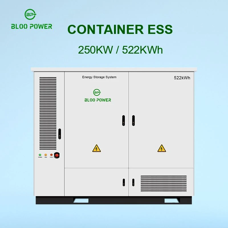
ESS 261 kWh / 125 kW liquid-cooled cabinet (314 Ah LFP, 260S1P, 832 V DC nominal) |
AC or DC side depending on the cluster's existing distribution; bidirectional conversion is integral |
Integrated 125 kW PCS, 99.0% peak conversion efficiency, THDi <3% on linear loads, grid peak-shaving and off-grid supply modes |
Lead-acid versus lithium iron phosphate on a base station
Moving an estate to lithium iron phosphate reorders the cost structure; the ¥0.504 per Wh price came from an operator-scale tender, not retail purchasing.
Valve-regulated lead-acid versus lithium iron phosphate for base station backup
|
Parameter |
Valve-regulated lead-acid |
Lithium iron phosphate |
Source |
|
Energy density |
38–40 Wh/kg |
170–180 Wh/kg (roughly 4–5× lead-acid) |
Industry performance compilation |
|
Cycle life |
1,000–1,200 cycles |
7,000–10,000 cycles (to 70% of rated capacity) |
As above |
|
Purchase price |
¥0.6–0.7 / Wh |
¥0.8–1.0 / Wh list; ¥0.504 / Wh average in a 2021 operator tender (≈US$0.07 / Wh) |
Price band; tender disclosure |
|
Discharge characteristic |
Less stable across depth of discharge |
Stable |
Broker research |
|
Safety profile |
Weaker |
Stronger; thermal runaway onset well above nickel-based chemistries |
Broker research; technical literature |
|
Environmental profile |
Contains lead; improper disposal creates secondary contamination |
No contamination during production or use |
Broker research |
|
End-of-life value |
High scrap value, recovery above 90% |
Recycling still maturing; now regulated under the EU battery framework |
Broker research; Regulation (EU) 2023/1542 |
|
Site backup duration |
2–3 h typical |
Extendable to the 7 h class |
Published retrofit scheme |
|
Annual replacement cost |
≈¥4,000 (≈US$555) per site |
Materially lower once cycle life is annualised |
As above |
|
Market inflection |
Tower procurement of lead-acid discontinued in 2018 |
Framework tenders in 2020 across three operators and one tower company specified about 4 GW |
Broker research |
Battery, MPPT and inverter interface matrix
This table carries the most operational value: it turns "windows must nest" into a commissioning checklist for a battery energy storage systems BESS manufacturer's hardware running against another vendor's inverter, and into the only place a second battery energy storage systems BESS manufacturer can be compared on equal terms.
Coupling requirements across the battery, MPPT and inverter interfaces
|
Interface |
Battery side (BP-HP-16KWH-B) |
MPPT side (48 V DC module) |
Inverter / PCS side |
Coupling requirement |
|
DC voltage range |
40–58.4 V |
42–60 V output (wide-window models) |
44.8–58.4 V input on 48 V models |
Inverter window must cover the battery's normal band; the MPPT output window must be wider than the battery window to leave adjustment room |
|
Charge voltage setpoint |
56.8–57.6 V (3.55–3.60 V/cell) |
Output ceiling ≥ 57.6 V plus cable drop |
Over-voltage trip > 57.6 V plus cable drop |
The difference between the three is the size of the "battery never fully charges" risk: a 0.4 V shortfall parks SOC at 95% |
|
Float voltage |
54.0–54.4 V |
Not applicable (charges only) |
Maintained by the site power system |
Float belongs to the rectifier controller; neither MPPT nor inverter should set it independently |
|
Continuous current |
200 A charge / 200 A discharge |
42 A per module, modules parallel |
240 A maximum on the hybrid inverter |
Inverter current capability must not be lower than the battery's allowable value, or the battery's power capability is wasted |
|
Communication |
CAN + RS485 |
RS485 / Modbus (some include CAN) |
CAN / RS485 / Ethernet (Modbus TCP) |
At least one channel compatible with the BMS for limit publication, and a second for the EMS or site monitoring |
|
Source of limits |
BMS calculates and broadcasts over CAN |
No BMS link; coordinates implicitly through bus voltage |
Receives BMS limits and clamps output accordingly |
The BMS supplies constraints, the inverter enforces them. The authority cannot be inverted |
|
Protection coordination |
Three-level BMS (cell / module / cluster) plus per-string fuse |
Reverse polarity, reverse current and surge protection |
Overcurrent, over- and under-voltage, anti-islanding |
The BMS current-limit message must precede the inverter's protection action, or the MPPT side absorbs a bus over-voltage |
|
Temperature window |
charge 0–50 °C / discharge −20 to +60 °C (32–122 °F / −4 to 140 °F) |
−40 to +65 °C (−40 to 149 °F) |
Model-dependent (cabinet −20 to +45 °C, derating above 45 °C) |
The system window is the intersection of all three; the low-temperature charge prohibition must be enforced by the BMS |
Seven lines for your procurement specification
These are hard requirements, not scoring points, because each maps to a specific field failure.
- Battery DC operating window and per-cell cut-off voltages - charge ceiling, discharge cut-off and float as three separate numbers. A nominal "48 V" is not an answer for lithium ion batteries for energy storage, and not one for a 48 volt lithium battery for off-grid cabinet either.
- Charge and discharge temperature windows stated separately. A single "−20 to 60 °C" band conceals the low-temperature charge prohibition, the most common cause of cold-climate failure on lithium ion batteries for energy storage.
- A complete BMS register map, and one link-loss fallback test at commissioning.
- Cycle life stated with its test conditions - 8,000 cycles at 80% depth of discharge, 0.5 C, 25 °C, to 70% health.
- A UL 9540A test report with the coverage level named, plus EU conformity, carbon footprint and battery passport readiness under Regulation (EU) 2023/1542[25] - documentation established lithium ion battery energy storage systems should already hold.
- A full efficiency-versus-load curve for the inverter or PCS, not a single peak figure - weighted efficiency across the 30–80% band, no-load loss included, and the figure a battery energy storage systems BESS manufacturer should be asked to publish.
- The low-temperature charge logic and, where heating is fitted, its consumption in kWh per day, counted into the backup runtime and into the best charge level for lithium ion batteries that the dispatch engine may command.
Matching BLOO POWER products across the chain
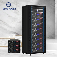
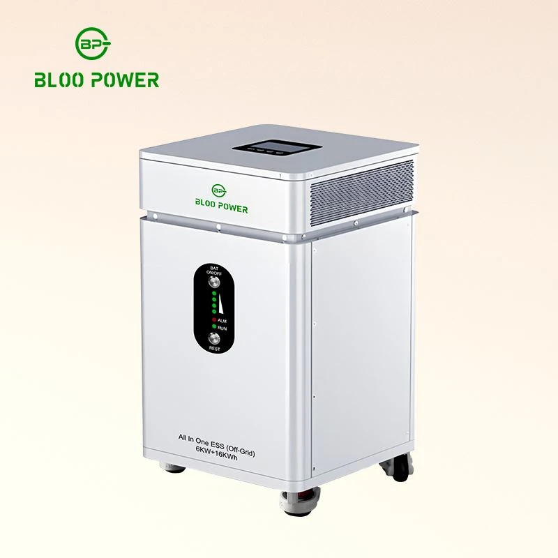
The BLOO POWER range covers four positions on one chain: a 3U rack battery for existing cabinets, a higher-capacity rack unit for 5G macro and off-grid sites, an integrated solar-storage system, and a liquid-cooled cabinet for cluster-level storage - serving lithium ion batteries for energy storage retrofits, 48 volt lithium battery for off-grid border sites and lithium-ion batteries for large-scale grid energy storage projects.
51.2 V (16S1P) / 150 Ah / 7.68 kWh; 40–58.4 V window, 43.2 V discharge cut-off
Charge −10 to +55 °C (14–131 °F), discharge 0 to +55 °C (32–131 °F); local LCD
RS485 and CAN, compatible with most off-grid and hybrid inverters and charge controllers
58 kg, 570 × 442 × 131 mm at 3U; up to 16 in parallel; 6,500 cycles; 15-year warranty
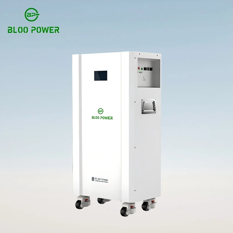
51.2 V (16S) / 314 Ah / 16 kWh; 40–58.4 V window
200 A maximum continuous charge and discharge; 80–90% usable depth of discharge
8,000 cycles at 80% DOD, round-trip efficiency >98%; IP66
Recommended charge 56.8–57.6 V (3.55–3.60 V/cell), float 54.0–54.4 V
Charge 0 to 50 °C, discharge −20 to +60 °C; 165 kg; up to 16 in parallel
51.2 V system in 100 / 200 / 300 Ah versions, i.e. 5.12 / 10.24 / 15.36 kWh
Supplied with 5 / 10 / 15 kW hybrid inverters: 48 V low-voltage battery, transformer-isolated
Six programmable charge and discharge windows, 240 A maximum, up to 10 in parallel, AC and DC coupling
Charge −10 to +55 °C, discharge 0 to +55 °C; up to 16 in parallel; 6,500 cycles
125 kW PCS, 99.0% peak conversion efficiency, THDi <3% on linear loads
314 Ah LFP cells, 260S1P, 832 V DC nominal (679–936 V)
>8,000 cycles at 80% DOD; liquid cooling holds cluster spread within 3 °C
Grid peak-shaving and off-grid supply modes; −20 to +45 °C operating range; IP55
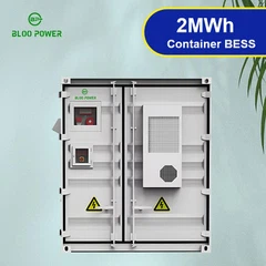
Perfluorohexanone gas suppression plus water sprinkler; noise <75 dB; 1,465 × 1,351 × 2,040 mm
|
Two limits on how to use this Every BLOO POWER parameter quoted here comes from published product pages and is a nominal figure; cell batches, BMS firmware and configuration can produce different measured results, so confirm selection against the type test report. The cost arithmetic in section 10 is a simplified model that excludes operations, degradation, insurance and fire protection. It is not investment advice and does not constitute an economic performance commitment.
|
Specify the whole energy chain with one supplier
BLOO POWER is a lithium iron phosphate cell manufacturer in Shenzhen with more than 17 years of battery engineering experience, a 15,000 m² base and 2 GWh of annual capacity, spanning 12 V and 24 V modules, rack-mounted home storage, solar-storage systems and industrial cabinets - so the 3U battery inside a base station cabinet and the 261 kWh liquid-cooled cabinet at a site cluster sit under one agreement. As a battery energy storage systems BESS manufacturer that also builds the hybrid inverter and the solar-storage system, we can turn a load schedule, a backup duration and the mounting conditions into a configuration proposal covering every interface in this guide. Tell us the load profile - lithium ion batteries for energy storage on a live DC plant, a 48 volt lithium battery for off-grid border site, or lithium-ion batteries for large-scale grid energy storage projects - and we will size it.
Send Inquiry