



















When Do Wall-Mounted Storage Batteries Need to Be Connected in Parallel?
Sep 21, 2026
Leave a message

Key takeaways
- Parallel connection adds capacity and discharge current without changing voltage. Wall-mounted units almost always use a series-first, parallel-second layout: 16 LiFePO4 cells in series to build a 51.2 V module, then identical modules linked in parallel to scale energy.
- Any one of five constraints can make it mandatory: insufficient energy, insufficient continuous power, insufficient backup duration, insufficient redundancy, or a market-access threshold the site cannot reach alone.
- The electrical limit and the compliance limit are different numbers. A manufacturer may permit 16 units in parallel; NFPA 855 may restrict an indoor location to roughly 40 kWh and an outdoor wall mount to about 80 kWh. The lower figure governs.
- Most parallel failures are installation failures, not product failures. Unequal cable lengths, mismatched module age and missing per-string protection create persistent circulating currents that show up a year or two later.
What "parallel" means for a wall-mounted battery
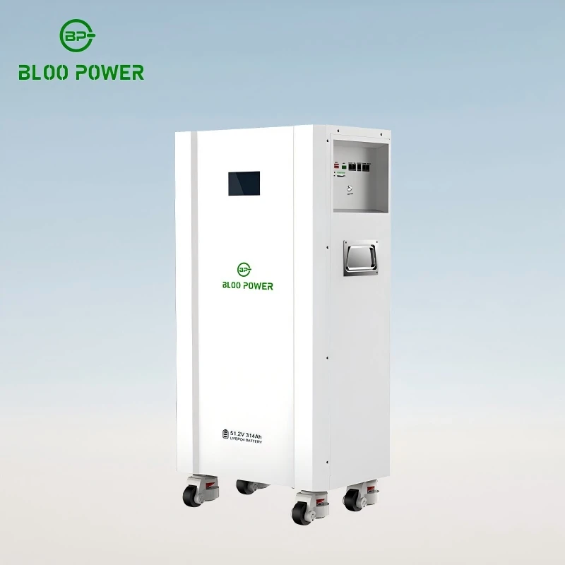
In a wall-mounted storage system, parallel connection means linking complete, self-managed battery modules to a shared DC bus so their capacities add up while the operating voltage stays where the inverter expects it. It is not a case of wiring individual cells together. BLOO POWER's BP-HP wall-mounted range, for example, builds every unit from 16 series-connected LiFePO4 cells (16S) at a 51.2 V nominal rating, with a usable voltage window of 40 V to 58.4 V. Capacity is then varied by changing cell capacity within that fixed configuration: 100 Ah for 5.12 kWh, 135 Ah for 6.91 kWh, 200 Ah for 10.24 kWh, and 300 Ah for 15.36 kWh.
That fixed 51.2 V platform is the reason parallel expansion works so cleanly in residential storage. Because every module presents the same voltage, a homeowner who starts with one unit can add another three years later without replacing the inverter, re-running the main DC cabling, or renegotiating the grid connection. What changes is simply the number of modules on the bus.
The practical ceiling on that number comes from three places, and it is worth naming them separately because they are often conflated. The BMS ceiling is how many units the master battery management system can address over its CAN or RS485 bus. The busbar ceiling is the current the shared DC conductors and terminals can carry. The compliance ceiling is the capacity your installation location is permitted to hold. A product datasheet will only tell you the first of the three.
Nominal platform shared across the entire BP-HP wall-mounted range, so modules remain electrically interchangeable
Maximum parallel connection declared in BLOO POWER's published wall-mounted specification
System capacity at the parallel ceiling, using the 10.24 kWh module
Rated cycles at 80% depth of discharge, the design life parallel expansion has to be planned around

Series, parallel, or both: choosing a topology
Series raises voltage and holds capacity constant. Parallel holds voltage constant and raises capacity. Residential storage uses both at once, in a specific order - and the order matters more than the topology name suggests.
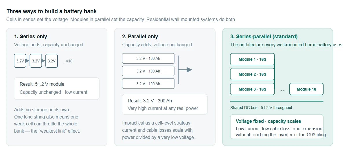
Figure 1 - Why residential storage lands on series-parallel. Series alone produces the right voltage but no added storage. Parallel alone produces storage but forces unmanageably high currents at a 3.2 V cell level. The hybrid keeps the working voltage at 51.2 V - where currents and cable cross-sections stay reasonable - while allowing capacity to be added one module at a time.
There is a second reason the hybrid wins, and it is the one manufacturers rarely put in the brochure. In a purely series arrangement, a degraded module drags the whole string down to its own capacity, and the string shuts off when the weakest module empties. In a parallel arrangement, each module contributes whatever it has. Enphase built its modular architecture around exactly this property, which is why its per-module expansion claims hold regardless of the age of the existing units. If you are specifying a system today with any expectation of expanding it in five years, parallelism is the choice that preserves that option.
Twelve situations that require parallel connection
The list below is organised by what has run out, rather than by product feature. If any single item applies, parallel expansion belongs in the design comparison. If two or more apply, it is usually no longer a question of whether to parallel but of how many units and in what configuration.
GROUP A Capacity-driven reasons
1. Daily consumption exceeds what a single unit can cover
This is the most common and least glamorous trigger. The sizing rule is not total generation - it is cyclable energy ≈ daytime PV surplus + evening load. Practical residential bands run from 5–10 kWh for a small apartment, 10–20 kWh for a typical family home, 20–40 kWh for a larger property, and 40 kWh upward for commercial or off-grid use. Once the calculation lands in the top two bands while a single wall-mounted unit tops out at 10.24 kWh or 15.36 kWh, parallel expansion is the only route. Three BP-HP-10KWH units give 30.72 kWh; five give 51.2 kWh, enough for a house running a heat pump and an EV charger. A useful side effect is that capacity and discharge capability scale together - five units lift the continuous discharge ceiling from 200 A to 1,000 A - so the existing inverter does not become the next bottleneck.
2. PV array output exceeds what a single unit can absorb
A 10 kWp array produces roughly 40–50 kWh on a clear day, and around 30% of that is surplus to daytime demand - somewhere between 12 and 15 kWh.Pair that array with a single 5.12 kWh unit and the absorption capacity is capped hard; the excess is exported at a low rate or curtailed, and self-consumption stalls in the 40–60% range. Move to two or three modules in parallel and the same array typically delivers 75–85% self-consumption. The economics improve not because tariffs moved, but because generation that was previously given away is now shifted into higher-value hours. The direction of travel across the market supports this: global residential storage shipments reached roughly 35 GWh in 2025, up close to 50% year on year, with cumulative installed capacity passing 187 GWh.
3. Off-grid autonomy has to span consecutive overcast days
Off-grid installations have the least tolerance for under-sizing because there is no grid to fall back on. A frequently cited reference point is a 4 kW array with 15 kWh of storage supporting a household drawing 5–10 kWh per day through one to three sunless days; extending autonomy to three to five days pushes the requirement to 30–50 kWh. Translated into wall-mounted hardware, 15 kWh is already close to one and a half 10.24 kWh units, so the practical specification is two units in parallel at 20.48 kWh with margin. The BP-HP-15KWH variant, rated IP66 and available in both wall-mounted and wheeled floor-standing form, is the more sensible starting point where outdoor placement is the only option. Size this from the longest consecutive overcast period on record for the site, not from average daily consumption - averaging is how off-grid systems end up in low-voltage shutdown in the middle of winter.
4. Backup duration targets translate directly into unit count
Outage protection is the clearest piece of arithmetic in the whole design process: minimum capacity = critical load (kW) × target hours ÷ depth of discharge ÷ round-trip efficiency. Take a typical critical-load circuit of a refrigerator at around 200 W, lighting and networking at around 150 W, and security or medical equipment at around 100 W - roughly 0.45 kW in total. Twenty-four hours of autonomy therefore needs about 10.8 kWh of usable energy, which at 80% depth of discharge and roughly 90% round-trip efficiency implies around 15 kWh of nameplate capacity. That is one BP-HP-15KWH unit, or two 10.24 kWh units in parallel at 20.48 kWh with useful headroom. Raise the target to 48 hours, or add air conditioning, a well pump or medical devices to the list, and the requirement jumps to 30–60 kWh - three to six modules. One discipline matters here: size for coincident peak load, not average load. Motor-driven loads draw three to five times their rated power at start-up, and parallel operation helps precisely because it raises the instantaneous output ceiling at the same time as the stored energy.
GROUP B Power-driven reasons
5. The constraint is discharge current, not stored energy
Most sizing conversations focus on kilowatt-hours and miss the harder limit sitting underneath. Every battery BMS caps continuous discharge current, and on wall-mounted hardware that cap is not generous. BLOO POWER's 5.12 kWh and 6.91 kWh BP-HP units are rated at 100 A continuous - about 5.12 kW - while the 10.24 kWh and 15.36 kWh variants reach 200 A.[12] Introduce a heat pump drawing 3–5 kW, a multi-split air conditioner at 4–8 kW, an instantaneous water heater at 6–9 kW or a 7–11 kW AC charger, and a single unit will trip its over-current protection and shut the whole system down. The battery may still be sitting at 80% state of charge; it simply cannot deliver the power. Two modules in parallel move the ceiling to 400 A, enough for a heat pump and an EV charger together; four modules reach 800 A, which is small-commercial territory. Where an existing PV system needs more power without disturbing the original grid-connection filing, parallel expansion is often the only route that does not trigger a new application.
6. A three-phase system needs more DC capacity, especially with unbalanced loads
Three-phase storage inverters are standard in larger homes and light commercial settings, and they place greater demands on the DC side than an equivalent single-phase machine. The reason is phase balancing: mainstream three-phase hybrid inverters support unbalanced input and output, but each still needs its own battery connection. In practice two parallel requirements emerge. First, a three-phase inverter in the 10–20 kW class typically wants 20–40 kWh of storage, which is two to four wall-mounted modules rather than one. Second, where single-phase loads on one leg are heavy, the system needs additional reserve to absorb the resulting inter-phase power difference so that no single leg's storage is driven into deep discharge. Once single-phase loads exceed about 30% of the total, sizing at 1.2 to 1.3 times the theoretical figure is a reasonable allowance. There is also a sequencing trap worth flagging: when installers parallel additional inverters to increase AC output, the DC side must expand in step, or the new inverters spend their life derated.
GROUP C Resilience and life-cycle reasons
7. The budget and the requirement do not arrive in the same year
This is where modular architecture earns its premium. Household demand is not a constant: an EV arrives this year, a heat pump next year, an extra occupant the year after, and each one rewrites the capacity model. Buy for the five-year peak up front and the owner carries the full capital cost and the full depreciation curve from day one. Buy only for today and growth forces an all-or-nothing replacement. Parallel design offers the third path - add a module as demand arrives, on the same inverter, the same master-slave BMS hierarchy and the same monitoring platform. BLOO POWER's residential range spans 5.12 kWh to 15.36 kWh in wall-mounted form, 15.36 kWh to 20.48 kWh in stacked form with a path to 30–45 kWh and beyond, all with parallel expansion declared. One rule is non-negotiable: expansion modules should match the existing units in model, production batch and approximate cycle count. Mixing batches converts a capacity upgrade into a circulating-current problem, which is the subject of a later section.
8. Uptime matters more than capacity
A single-unit system has the availability of a single unit. One BMS fault, one contactor failure, one module going out of balance, and the house is dark. Parallel operation makes an N+1 topology possible: N modules carry the load in normal operation, and if one fails or needs to come offline for service, the remainder keeps the critical circuits running. That is a genuine requirement for homes with medical equipment, elderly occupants, home-based businesses or remote communications equipment. Reliability engineering frames the benefit clearly - if a single unit has annual failure probability λ, the probability that an N-unit parallel system loses all capacity is a joint probability rather than a single point of failure, and availability improves by orders of magnitude rather than percentages. Three design details make the redundancy real rather than nominal: a dedicated DC fuse or breaker on every string so a fault can be isolated physically, the ability to withdraw one module without de-energising the bus, and a master-slave BMS that can hand over communications if the master drops out. BLOO POWER's wall-mounted units ship with an integrated BMS providing over-temperature, over-voltage and over-current protection plus CAN/RS485 communication, which is the substrate those strategies need.
9. Existing systems age out of balance, and expansion has to respect that
Home storage is increasingly a retrofit market, which means expansion usually happens on top of hardware that has already been cycling for years. A battery that has run daily for 30 months may sit at 88% or 92% of its original capacity. Bolting a new module onto that bus creates a genuine age mismatch, and an open-circuit voltage difference of just 0.5 V is enough to drive measurable circulating current. The engineering rule is measure before you parallel: compare static open-circuit voltage spread and internal resistance dispersion across the existing strings, then decide. Where the spread is tight, matched modules can join the same bus. Where it is wide, the sounder approach is to run new modules as a separate string with their own BMS and let a supervisory controller coordinate the two - not to tie new and old hardware to a common busbar. Full CAN/RS485 support throughout the BLOO POWER range makes that layered arrangement straightforward to commission.
GROUP D Economic and market reasons
10. Peak-valley arbitrage needs throughput, and throughput scales with capacity
Under a time-of-use tariff, annual arbitrage revenue approximates to daily cycled energy × peak-to-off-peak spread × operating days × round-trip efficiency. The only term that design decisions can enlarge directly is daily cycled energy. A 15 kWh system cycling against a 0.6 RMB/kWh spread returns roughly 9 RMB a day, or about 3,200 RMB a year; double the capacity and the return roughly doubles with it. There is a caveat that matters. Spreads are narrowing - the average difference between peak and off-peak grid purchase prices across 32 Chinese regions fell to 0.616 RMB/kWh in 2025, down 9.4% year on year, with time-band definitions also shifting as spot markets are phased in. The era in which a small battery could pay for itself on a wide spread alone is closing; future returns depend on scale and intelligent dispatch together. Just as importantly, the marginal return on added capacity is not linear. Once the bank is much larger than the cyclable energy available each day, the extra modules run a single shallow cycle daily, annual equivalent cycles fall, and the payback period lengthens. Model a full year of interval data before deciding on unit count.
11. Virtual power plant and demand-response programmes have entry thresholds
Residential storage is shifting from a pure backup appliance to a revenue-generating asset. In 2025, 43% of home storage systems shipped with an intelligent energy management function attached, a figure expected to pass 50% in 2026, and aggregator-led participation in frequency-response markets has been validated in Germany, Australia and California. These programmes impose entry requirements on individual sites - commonly a minimum dispatchable energy and power rating, typically in the 5–10 kWh and 3–5 kW range, plus remote dispatch capability, state-of-charge reporting and fast response. A single 5.12 kWh unit frequently sits just below that line. Two units in parallel at 10.24 kWh and around 10 kW clears it. This is a threshold effect rather than a gradual benefit: the system either qualifies as a market participant or it does not, and clearing the line is what turns a bill-reduction asset into an income-producing one. It is one of the structural reasons global average residential storage payback has compressed to about 7.8 years, and to around 5.2 years in high-tariff markets such as Italy.
12. Small commercial and specialist loads sit between residential and industrial
The parallel capability of wall-mounted hardware is steadily pushing its useful range beyond the home. A telecoms site needs 24-hour continuity and is often sited where the grid is absent or unreliable; typical loads of 1–3 kW over 8–24 hours imply 10–40 kWh, or one to four 10.24 kWh modules. An agricultural pump draws 3–7.5 kW in intense daytime pulses, where two or three units in parallel absorb the intermittency of the array driving it. A solar-plus-charging hub is the clearest power-driven case of all: a single 7 kW AC charger on top of site lighting and retail load routinely totals 10–15 kW, which needs four or more modules to sustain. What these applications share is concentrated load, high power density and no plant room - which is exactly where a wall-mounted enclosure earns its place, mounted on a distribution-room wall, a container side or a pump-house exterior, with IP65 or IP66 protection for outdoor duty.The market context supports the move: Chinese user-side storage added 5.3 GW and 13.7 GWh in 2025, up 96.5% in power and 115.2% in energy year on year, making it the fastest-growing segment in the sector.
How many units can you actually link?
The honest answer is that two separate numbers apply, and the smaller one governs. The electrical ceiling is what the manufacturer declares for the product. The compliance ceiling is what the installation location permits. Manufacturers publish the first prominently and mention the second rarely, which is how designs end up technically sound and administratively unapprovable.
Parallel expansion capacity across the BLOO POWER residential range (from published product data)
|
Product |
Energy per unit |
Nominal voltage |
Continuous discharge |
Parallel ceiling |
System capacity at ceiling |
|
|
BP-HP-5KWH-C / -A |
5.12 kWh (100 Ah) |
51.2 V |
100 A / 5.12 kW |
16 units |
81.9 kWh |
|
|
BP-HP-7KWH-C / -A |
6.91 kWh (135 Ah) |
51.2 V |
100 A |
16 units |
110.6 kWh |
|
|
BP-HP-10KWH-C / -A |
10.24 kWh (200 Ah) |
51.2 V |
200 A / 10.24 kW |
16 units |
163.8 kWh |
|
|
BP-HP-15KWH-C (wall or wheeled, IP66) |
15.36 kWh (300 Ah) |
51.2 V |
200 A |
16 units |
245.8 kWh |
|
|
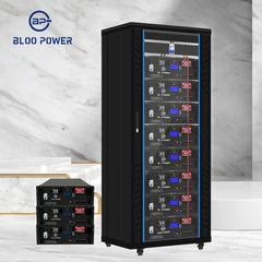
BP-HB-LV-15KWH (stacked) |
15.36 kWh |
51.2 V |
≈150 A |
Modular, to 30–45 kWh+ |
45 kWh+ |
|
|
Rack-mounted 3U, 48 V |
5.12 / 10.24 kWh |
51.2 V |
- |
Modular, to 30 kWh+ |
30 kWh+ |
|
|
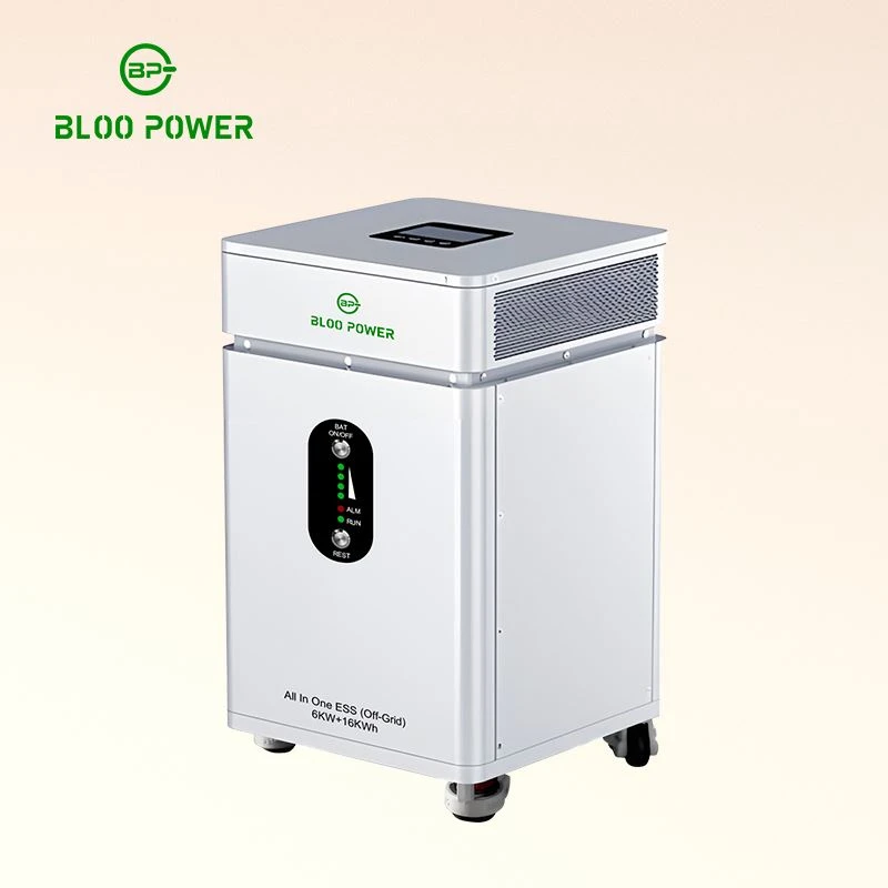
All-in-One ESS |
16 kWh (incl. 6 kW inverter) |
51.2 V · 314 Ah |
- |
Parallel expansion supported |
Scales with unit count |
|
Shared across the BP-HP range: 16S cell configuration, 40–58.4 V operating window, 6,500 cycles at 80% depth of discharge, charge temperature −10 °C to 55 °C, discharge 0 °C to 55 °C, CAN/RS485 communication (RS232 on selected models), integrated BMS, and compatibility with mainstream off-grid and hybrid inverters. Certification covers CE, FCC, MSDS and UN38.3, with UL 1973 and IEC 62619 available on selected models.
For context on where that ceiling sits relative to competitors: FranklinWH's aPower 2 declares 15 kWh per unit with up to 15 units in parallel per aGate controller, giving a 225 kWh system maximum. Tesla took the opposite route with the Powerwall 3, shipping a sealed 13.5 kWh unit where expansion means adding another complete Powerwall rather than stacking modules. Both approaches are defensible - the trade-off is granularity against integration simplicity - but only one of them lets a homeowner add 10 kWh without buying 13.5.
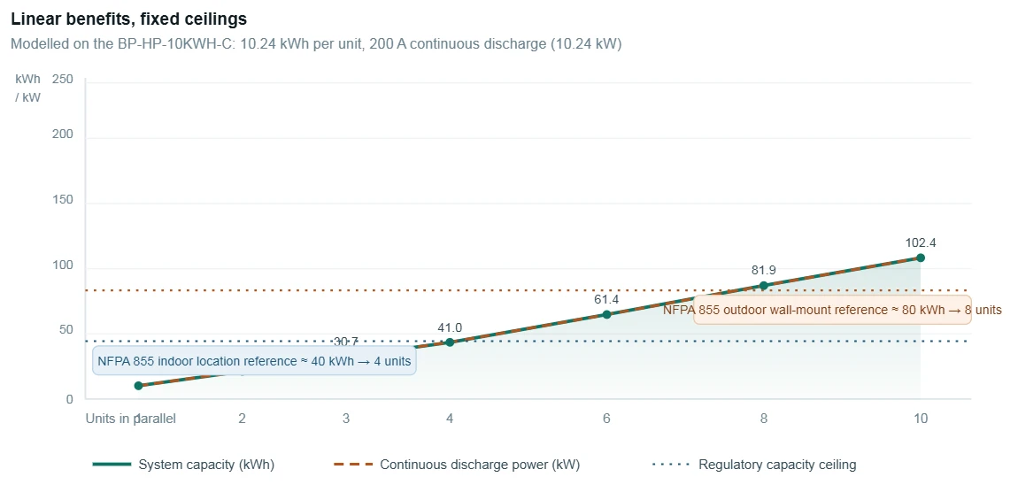
Figure 2 - Capability scales linearly; permission does not. On a fixed 51.2 V platform, every added 10.24 kWh / 200 A module raises stored energy and discharge power in step - the two lines coincide. Regulatory capacity limits do not move with unit count: under NFPA 855 an indoor location is commonly capped at around 40 kWh and an outdoor wall mount at about 80 kWh, with 3 ft (0.9 m) separation between units unless the assembly has been tested as a group to UL 9540A.
The circulating current problem
Parallel connection has one characteristic failure mode, and it is almost always an installation issue rather than a product defect. When two or more strings share a bus, any difference in their open-circuit voltage drives current between them - irrespective of whether the system is supplying a load. With one string at 85% state of charge (around 54.4 V) and another at 72% (around 52.8 V), a 1.6 V difference across roughly 25 milliohms of combined internal, cable and busbar resistance produces a continuous internal current in the region of 35 A. That current does no useful work. It converts entirely to heat, runs 24 hours a day, and pulls both strings further from balance while potentially triggering protective shutdowns on both BMS units.

Figure 3 - Where parallel banks quietly fail. SoC mismatch produces a permanent internal current that no load caused. Cable length mismatch redistributes load current in inverse proportion to resistance. IEC 62619 treats uniform current sharing as a design requirement for parallel configurations rather than an optional refinement.
Neither failure appears on a commissioning report. Both usually surface 12 to 24 months later, as one string measurably weaker than the others. The preventive measures are inexpensive and procedural:
- Match the modules. Same model, same production batch, comparable cycle count. Where an existing system is being expanded, measure before committing.
- Cut every parallel cable to the same length. Same cross-section, same routing. If one run is 1.2 m, all runs are 1.2 m - secure the excess with cable ties rather than trimming.
- Protect each string separately. NEC 706.31 requires overcurrent protection on every parallel-connected battery or string, rated to protect the conductors.
- Provide a means to disconnect. NEC 706.15 requires a disconnecting means capable of de-energising all ungrounded conductors, rated for DC at system voltage. AC-rated devices are not an acceptable substitute.
- Pre-charge before closing. A 50–100 Ω resistor rated for at least 50 W limits the inrush when strings are first paralleled.
- Verify SoC synchronisation. Confirm through the CAN or RS485 link that all units report comparable state of charge before energising the bus.
Compliance ceilings: United States, United Kingdom, EU and Australia
Capacity limits are jurisdictional, and they are the constraint homeowners and installers most often discover late. The frameworks below are the ones that determine how much storage a given location may hold - which in turn determines the maximum sensible unit count, regardless of what the datasheet allows.
How parallel expansion interacts with residential storage rules by market
|
Market |
Governing documents |
Capacity and siting limits |
What this means for unit count |
|
United States |
NFPA 855 (2023), UL 9540 / UL 9540A, NEC Article 706, IRC R328, IFC 1206 |
Single ESS unit ≤ 20 kWh. Indoor installation location (garage, utility room, basement) ≈ 40 kWh. Outdoor wall mount ≈ 80 kWh. Room-level maximum allowable quantity 600 kWh. No batteries in bedrooms, living rooms or kitchens. |
Two 10.24 kWh units fit a garage; three or more generally require an outdoor location or a UL 9540A group-tested product. Without group testing, units need about 3 ft (0.9 m) separation on all sides. |
|
United Kingdom |
BS 7671:2018+A4:2026 Chapter 57, PAS 63100:2024, MCS MIS 3012, IET Code of Practice (3rd ed.), ENA G98 / G99 |
No simple kWh cap; the constraint is siting. Batteries are excluded from rooms used for sleeping, from lofts, and from protected escape routes. Externally mounted units need roughly 1 m clearance from windows, doors and vents. G98 covers notify-and-connect up to 3.68 kW per phase, G99 above it. |
Expansion is governed by location rather than unit count. Critically, alterations and additions after 15 October 2026 must satisfy the new rules - so adding a module to a loft-mounted system can force relocation of the whole installation. |
|
European Union |
IEC 62619, IEC 63056, IEC 62109; national overlays including VDE-AR-E 2510-50 (Germany); EU Battery Regulation (EU) 2023/1542 |
Product-level safety and lifecycle requirements are harmonised through IEC; siting and installation rules are set nationally. VDE-AR-E 2510-50 is routinely requested in the German residential market and carries practical weight with installers and insurers. |
IEC 62619 requires uniform current sharing as a design condition, which makes compliant parallel operation a product-level obligation. National overlays still need individual verification per member state. |
|
Australia / New Zealand |
AS/NZS 5139:2019+A1, AS/NZS 3001.2:2022 |
Applies to 12–1500 V DC systems and to individual BESS units from 1 kWh to 200 kWh. Lithium cells are classified as fire hazard Level 1 (self-sustaining combustion). No installation in habitable rooms; ≥600 mm from any exit, ≥1 m clear access in front. |
Where an installation includes multiple systems, each is assessed individually - the standard explicitly prevents splitting capacity across separate units to avoid the thresholds. |
|
China |
GB/T 36276-2023, GB 44240-2024 |
Voluntary in law but treated as a tender requirement for grid-side and renewable-linked projects. Cell capacity deviation ≤3%, internal resistance deviation ≤20%, ≥80% capacity retention after 5,000 cycles. |
The 2023 revision added a thermal runaway propagation suppression test and tightened insulation and dielectric requirements at module and string level - directly relevant to multi-unit assemblies. |
The rule that catches people out
In the UK, an installation that complied with the regulations in force at the time remains compliant - the rules are not retrospective. But any alteration or addition made after 15 October 2026 must meet Chapter 57 of BS 7671. Adding a single module to an existing system is an alteration. If the battery sits in a location the new rules exclude, expansion can mean relocation rather than simply another unit.
When parallel connection is the wrong answer
Getting the direction right matters, because a badly executed parallel bank costs more than a correctly sized single unit - not immediately, but as a degradation problem two years down the line. Three situations argue against paralleling.
Mismatched modules should not be paralleled at all
IEC 62619 makes uniform current sharing a design requirement for parallel configurations,[9] and achieving it depends on tight parameter spread. Chinese second-life battery specifications offer usable quantitative thresholds: static open-circuit voltage deviation within 300 mV of the average, internal resistance dispersion below 5%, and energy dispersion below 10%, with parallel limits of four units at or below 60 V and two units above it. Those figures apply to repurposed cells, but the consistency logic transfers to any parallel design. If the spread is wide, the answer is separate strings under a supervisory controller, not a shared busbar.
When the compliance ceiling is reached, change the location, not the wiring
If a design needs a fifth module and the chosen location is capped at roughly 40 kWh, adding it anyway does not solve the problem - it creates a non-compliant installation. The legitimate options are to move the system outdoors or into a garage, to select a product that has passed UL 9540A as a group assembly (which can allow closer spacing and higher allowances at the authority's discretion), or to split the capacity across separate fire-separated spaces and assess each independently.
When capacity is already sufficient, more units lengthen payback
Overbuilding is a real and common error. Once the bank substantially exceeds the cyclable energy available each day, the surplus modules run one shallow cycle a day, equivalent annual cycles fall, and the return on that capital declines - while purchase cost, floor or wall loading, and maintenance complexity all rise. Weight is part of the practical picture too: a 10.24 kWh unit weighs around 120 kg and a 15.36 kWh unit around 165 kg,so continuous wall-mounted arrays require a proper assessment of the supporting structure. The sensible sequence is to model 8,760 hours of consumption and generation first, identify the optimal capacity band, and only then convert that band into a unit count.
A five-step sizing workflow
Condensed into a sequence that can be worked through in order without skipping steps:
- Establish the load baseline. Pull at least twelve months of interval data from the meter or the utility portal. Establish daily consumption, the daytime-to-evening split, seasonal peaks, and the highest coincident peak load. This sets both the energy floor and the power floor.
- Calculate cyclable energy, not total consumption. Estimate daytime PV surplus plus evening load. Using annual consumption instead of cyclable energy is the single most common cause of oversizing.
- Size twice and take the larger result. Run the calculation once on capacity and once on continuous discharge current, then add 15–25% margin and round up to whole units. On a 10.24 kWh module, 200 A continuous discharge is the power-side reference figure.
- Screen the compliance limits. Confirm the capacity ceiling attached to the proposed location, clearance to windows, doors, vents and escape routes, and the load-bearing capacity of the wall or floor.
- Lock in the wiring method. Matched modules, equal-length and equal-cross-section cable runs, a dedicated overcurrent device per string, a DC-rated disconnecting means, and a pre-charge step at first energisation.
The short version
A wall-mounted battery needs parallel connection when one of five things runs out: energy, power, duration, resilience or market access. Whether that parallel bank performs as designed comes down to three conditions holding at once - matched parameters, disciplined wiring, and a location whose capacity ceiling you have not crossed.

Planning a system that may need to grow?
BLOO POWER's residential range runs from 5.12 kWh wall-mounted modules to 16 kWh all-in-one systems, all on a shared 51.2 V platform with parallel expansion declared, integrated BMS, and CAN/RS485 communication. Send us your load profile, array size and intended installation location, and our engineering team will return a sizing calculation together with the unit count and wiring method that fits both your ceiling and your compliance pathway.
Send Inquiry