




















Why BMS Matters for Telecom Base Station Batteries?
Oct 08, 2026
Leave a message

|
What this guide answers
|
The first-principles shift: a spare part became a managed asset
For roughly twenty years the battery at a telecom site was the least interesting object in the cabinet. A string of 48 V valve-regulated lead-acid blocks sat on float, discharged during an outage, and was replaced as a set every three or four years. That arrangement survived because lead-acid fails slowly and legibly: it sulfates, it dries out, it loses capacity, and its overcharge behaviour is self-limiting, because the voltage sags back and charge acceptance falls away. Nobody had to watch it closely.
5G dismantled that. GSMA's Mobile Economy 2026 counts 8.8 billion mobile connections worldwide serving around 5.8 billion people, and notes that more than 390 operators had launched commercial 5G across roughly 160 countries as of May 2026, with global 5G connections forecast to reach 3.4 billion by the end of 2026, about 37 percent of all connections. In the United States, CTIA's 2026 annual survey reports 442,000 cell sites supporting wireless service in 2025, of which close to 40 percent are small cells, alongside 159.3 trillion megabytes of mobile data traffic - a 20 percent increase in a single year - and nearly 30 billion dollars of network capital investment in that same year. Sites keep getting denser, and every new site draws far more than the equipment it displaced.
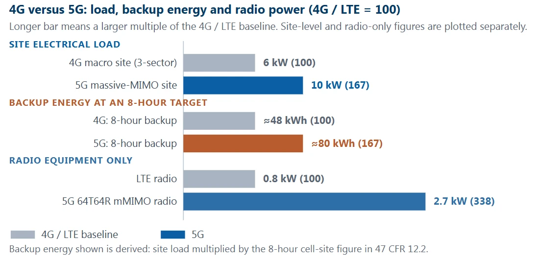
Figure 1 · Site load from ACG Research (Chris Nicoll), reported by Light Reading: a 4G three-sector, 12-radio site draws about 6 kW and a 5G massive-MIMO site about 10 kW. Radio-only figures from ABI Research: a 5G RAN in a 64T64R massive-MIMO configuration draws up to 2.7 kW against roughly 0.8 kW for an LTE radio, and ABI states that a 5G base station needs about three times the energy of 4G to deliver equivalent coverage, with over 70 percent of network energy consumed in the radio access network. Backup energy is a derived illustration using the 8-hour cell-site figure originally set in FCC rule 47 CFR 12.2 and later withdrawn; it is not a regulatory requirement today. Published Chinese-market evidence points the same way - China Tower has reported a single-tenant average of about 3.8 kW per 5G outdoor site, more than three times an equivalent 4G site - and is presented here as a published observation, not as a global average.
Load is only half of it. Put a backup obligation on top and the arithmetic becomes uncomfortable. The FCC's post-Katrina rule, 47 CFR 12.2, required 24 hours of emergency backup inside central offices and eight hours at cell sites; the wireless industry challenged it, the rule was stayed in 2008 and formally deleted in 2011, so there is no federal backup mandate in the United States today. What replaced it is a patchwork: California's Public Utilities Commission requires 72 hours of backup power for cell sites in Tier 2 and Tier 3 High Fire Threat Districts, NEC Article 708 pulls public-safety sites into Critical Operations Power System territory, and beyond that the requirement comes from service-level agreements, insurers and local authorities. Whatever number a project adopts, the same multiplication applies. Eight hours at 6 kW is roughly 48 kWh; eight hours at 10 kW is roughly 80 kWh; 72 hours at 10 kW is 720 kWh, which is why wildfire-zone sites are generator sites and not battery sites. That last figure is not a failure of battery technology. It is the boundary of the technology, and it is worth writing down early.
But the genuinely disruptive change is not that sites need more energy. It is that the energy behaves differently. Lead-acid is self-limiting on overcharge; LiFePO4 is not. On sustained overcharge a LiFePO4 cell keeps climbing in voltage while heat accumulates inside a sealed can, and once the heat generated by decomposition exceeds what the can can dissipate, the reaction accelerates on its own. At the same time, LiFePO4's energy density is exactly what lets a bank move into a smaller cabinet, higher on a rooftop, in a hotter ambient - and a cell site is precisely the place that is unattended, thermally hostile, space-constrained and expensive to fail. Operations organisations are built to absorb predictable slow degradation, not unpredictable fast failure.
That is why everyone who has worked through a lithium-for-lead replacement seriously converges on the same conclusion: the first selection decision is not the cell, it is the BMS. Unattended operation is what creates the entire requirement for a BMS for telecom base station batteries. It has to stand in for the engineer who used to arrive with a multimeter, and do the sampling, judging, balancing, protecting, reporting and record-keeping that person used to do. The twelve points below work through what that means in engineering terms.
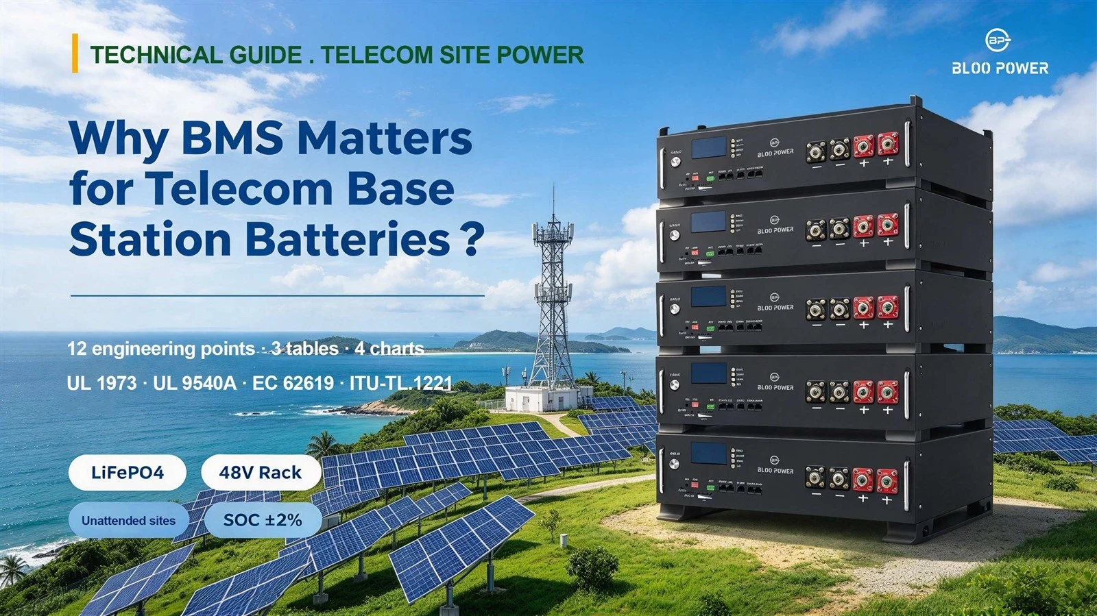
The battery stops being a passive component and becomes a controlled system
Lead-acid management can be summarised as "set a float voltage and stop thinking about it." The rectifier holds the 48 V bus at a fixed voltage, the string absorbs current on its own, and no active intervention is needed. Three properties made that work: lead-acid cells have a high nominal voltage (2 V), so a 48 V string needs only 24 of them; the cell count is low enough that mismatch is tolerable; and the voltage-to-charge relationship is blunt enough that the string behaves predictably across a wide range. Lithium reverses all three. A LiFePO4 cell is nominally 3.2 V, so a 48 V system needs 15 or 16 in series; every extra series element multiplies the probability of mismatch; and the LiFePO4 voltage-to-charge relationship is so flat that voltage carries almost no usable state information. A string built this way needs something that inspects, computes and intervenes cell by cell. That something is the BMS.
This is why the BMS is not an accessory. It is the precondition that makes the chemistry usable in an engineered product. BLOO POWER builds it as standard: every BP-BSB 3U rack module carries an integrated battery management system providing over-charge, over-discharge, over-current, short-circuit and over-temperature protection, and reports status over RS485 or CAN. The published parameter table for the series also lists the BMS as supporting SNMP together with a remote monitoring and management system. In today's procurement vocabulary, "48 V LiFePO4 module" already implies a BMS. When a supplier offers a battery without one, the thing on sale is not a semi-finished product; it is a component that cannot be used safely at a cell site.
There is a second consequence that procurement teams tend to notice later. Once the BMS exists, the battery acquires behaviour: it can refuse to charge, it can derate, it can report, it can log. That behaviour has to be specified, because a default that suits a residential wall unit may be wrong for a site whose entire value is measured in outage minutes. Two identical cells, one BMS configured for maximum cycle life and one configured for maximum runtime, produce two different products. The specification, not the cell datasheet, decides which one you bought.
The safety floor: keeping thermal runaway inside the cell
Choosing LiFePO4 for site storage is fundamentally a trade of energy density for safety margin. Industry technical literature places the onset of thermal runaway for LiFePO4 in the region of 200 to 270 °C, against roughly 150 to 210 °C for nickel-manganese-cobalt chemistries; more importantly, the phosphate structure does not release oxygen when it decomposes, so a LiFePO4 cell has no internal oxygen supply and its peak cell temperature typically stays in the 400 to 500 °C band, where an NMC cell can reach 600 to 900 °C or more. The practical difference is that LiFePO4 failure tends to smoulder rather than jet, which makes propagation much harder.
None of that makes LiFePO4 immune. At high state of charge, under sustained overcharge, or after a severe internal short, it still enters an irreversible self-heating chain. The last segment of that defence belongs to the BMS and nowhere else: compare every cell against its voltage ceiling continuously and break the charge path the moment an overcharge trend appears; derate and call for cooling when a temperature threshold is crossed; open the main path and raise an alarm when a hard threshold is crossed. What international practice uses to test how reliable that defence actually is, is the four-tier structure of UL 9540A - cell, module, unit and installation - which answers in sequence whether a single cell ignites, whether runaway propagates inside the module, whether flame escapes the enclosure, and whether an adjacent unit a metre away is affected. UL 9540A is a test method rather than a certification, and it is the consensus fire test explicitly cited by NFPA 855 for installation approval; the sixth edition was published in March 2026 and takes effect on 1 January 2027, so a 2026 project may legitimately receive a report against an earlier edition. The test is also a pointed interrogation of the BMS design, because if system-level thermal management, alarm tiers and cut-off logic are weak, any tier in that sequence can show propagation.
Two other standards sit underneath the BMS itself. IEC 62619:2022 sets safety requirements for secondary lithium cells and batteries in industrial applications and explicitly covers stationary uses including telecom, making it the umbrella document for this product class; IEC 63056:2020 addresses safety for lithium cells and batteries used in electrical energy storage systems up to 1,500 V DC. In North America, UL 1973 evaluates batteries for stationary and motive auxiliary applications - photovoltaic, wind, UPS and backup power among them - and is the component-level evaluation that normally precedes a system-level UL 9540 assessment. For a buyer, the practical rule is to ask which standard was applied, to which model, in which configuration, and whether the report actually covers the unit being purchased rather than a sibling.
Table 1 · Lead-acid, LiFePO4 and BMS compared by capability
Two mainstream site backup options compared item by item on management capability
|
Dimension |
Valve-regulated lead-acid (VRLA) |
LiFePO4 with no effective BMS |
LiFePO4 with a complete BMS |
|
48 V string construction |
2 V × 24 cells |
3.2 V × 15–16 cells |
Same, sampled cell by cell |
|
Voltage-to-SOC observability |
Reasonably continuous, can be read approximately |
Plateau extremely flat, voltage method fails |
Coulomb counting with anchor resets, or model-based estimation; steady-state error to ±2% |
|
Tolerance of mismatch |
Higher, equalising charge can pull it back |
Very low; weakest cell sets string capacity |
Balancing current 50–300 mA passive, 1–5 A active |
|
Hot environment |
Life falls sharply above 35 °C |
Ageing accelerates with no thermal management |
Multi-point sensing, derating, charge inhibit |
|
Charging below 0 °C |
Charge acceptance falls |
Lithium plating, permanent damage |
Charge inhibited as soon as any cell is below 0 °C |
|
Behaviour on overcharge |
Voltage sags back, gassing |
Voltage keeps climbing, heat accumulates, thermal runaway possible |
Cell-level over-voltage threshold opens the path and logs the event |
|
Status reporting |
Usually none |
None |
SOC, SOH, cell voltage, temperature and alarms all uploaded |
|
Remote access |
Mostly dry contacts or none |
None |
RS485, CAN, Modbus, SNMP |
|
How failure is found |
Scheduled manual inspection plus discharge test |
Only when an outage reveals it |
Trend-based early warning, exception-driven dispatch |
|
Replacement logic |
Whole string every 3–4 years |
Not usable |
Targeted replacement at an SOH threshold, with warranty data retained |
This table is an engineering comparison intended to help procurement and design teams separate what the battery can do from what the management system can do. Lead-acid cycle life and replacement interval figures follow the industry analysis in reference ; balancing current and usable-capacity recovery figures follow reference; SOC estimation figures follow references and . Live projects should work from the supplier's final confirmed datasheet.
Cell-to-cell variation: the weakest cell sets the group's usable capacity
This is the most counter-intuitive fact in lithium system design, and the one most often missed in procurement documents: the usable capacity of a series string is set not by the average cell but by the weakest cell. The physics is simple. In a series circuit the current is identical everywhere and the voltages add. During charge, as soon as any one cell reaches its cut-off voltage - around 3.65 V for LiFePO4 - the BMS must terminate charging for the whole string to protect it, even though the other fifteen cells may be 3 to 5 percent short of full. During discharge the logic runs the other way: as soon as any cell touches its discharge cut-off, around 2.5 V, the BMS must open the circuit, and the energy still sitting in the other cells is unreachable.
The published quantification is striking. Industry technical literature describes a 48 V / 200 Ah pack that could deliver only 60 percent of its rated capacity after 14 months even though roughly 95 percent of its cell capacity was intact. The missing 40 percent was not degradation; it was capacity the pack could no longer reach. The causes stack up: factory capacity tolerance of 1 to 5 percent, cell-to-cell differences in self-discharge rate that shift the starting point of every cycle, internal resistance differences that make cells behave differently under high current, and the most insidious one, thermal gradient - an unventilated corner of a rack can sit 10 to 15 °C above the centre, and the cells there age faster.
Balancing is the BMS's answer to that stack. Passive balancing bleeds excess energy from the highest-voltage cell as heat, typically at 50 to 300 mA. Active balancing moves energy between cells through a DC-DC stage, typically at 1 to 5 A and 85 to 95 percent efficiency. Industry technical literature commonly credits active balancing with recovering an additional 5 to 10 percent of usable capacity relative to passive balancing on large stationary systems. That is not a rounding error. On a 5G macro site whose backup requirement is in the 21 kWh region, a 10 percent usable-capacity difference is more than half an hour of runtime - the difference between clearing an outage window and not clearing it. BLOO POWER publishes an industrial-grade BMS with independent temperature sampling per cell string, voltage sampling accuracy of ±8 mV, and a 1 A active-balance stage that holds cell voltage spread within about 50 mV, which is the design response to exactly this problem.
SOC estimation: the blind spot on the LiFePO4 plateau
In the lead-acid era a technician could put a meter on a rested string and read the state of charge off the open-circuit voltage, because lead-acid OCV tracks SOC fairly continuously. LiFePO4 removes that option. The chart below plots open-circuit voltage against SOC for a LiFePO4 cell and an NMC cell on the same axes; note the shape of the LiFePO4 line through the middle of the range.
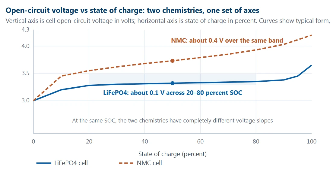
Figure 2 · Curves are typical forms intended to illustrate the observability difference between the two chemistries and do not represent a specific cell's measured data. The engineering basis is well established: over the LiFePO4 discharge plateau the voltage change is so small that industry technical literature describes a span of under roughly 50 mV across a 10 to 90 percent SOC window, which makes voltage-based SOC estimation unusable in that band.
Read the LiFePO4 curve closely. Between 20 and 80 percent SOC - the band a site battery lives in every day - the cell climbs from roughly 3.28 V to roughly 3.35 V, a total swing under 0.1 V. The voltage difference between 55 percent SOC and 70 percent SOC can be a few millivolts, which is smaller than the temperature drift of the sampling circuit. Reading state of charge from voltage under those conditions is like reading a road sign through fog.
Engineering has to substitute a different method. Coulomb counting - integrating current over time - is the mainstream real-time technique and is accurate over short horizons, but it accumulates error: current-sensor tolerance, temperature-dependent capacity change and currents too small to sample all push the integral away from the truth. Published BMS guidance describes drift of 2 to 5 percent within days if the estimate is never recalibrated. So an anchor reset is mandatory: force SOC to 100 percent when the pack genuinely reaches its full-charge voltage, and to 0 percent when it genuinely reaches discharge cut-off. A higher tier of design uses a model-based estimator such as an extended Kalman filter, which fuses coulomb counting with an equivalent-circuit or electrochemical model and continuously corrects the estimate using the difference between predicted and measured voltage, so it degrades more gracefully on the plateau and under temperature and ageing effects.
A 2025 paper in Applied Energy proposed an adaptive robust extended Kalman filter for LiFePO4 cells with pronounced voltage plateaus and held steady-state estimation error within ±2 percent under multi-temperature, noisy and disturbed test conditions. Published comparisons of the three families of method put OCV-based estimation at ±5 to 10 percent in the plateau band, short-term coulomb counting at ±3 to 5 percent with drift, and model-based estimation at ±1 to 2 percent. This is why the procurement question is not "does it display SOC" but "which method does it use, what resets it, and has the model been calibrated on the exact cell you are buying". The BLOO POWER base station module publishes SOC, SOH, cell voltage, temperature and event alarms, with SNMP and a supporting remote monitoring system; the value of that data stream is entirely bounded by the reliability of the estimator behind it.
Temperature: the night watchman across −20 to 65 °C
Site storage faces a harsher temperature regime than any consumer battery. The published operating range for the BLOO POWER BP-BSB rack series is −20 to 65 °C (−4 to 149 °F), and China Tower has deployed its own fully immersed storage units rated for stable operation from −30 to 55 °C with up to 72 hours of backup. Behind every one of those numbers is a direct demand on thermal management capability. Temperature matters because lithium is punished from both ends. On the hot side, cabinet interiors routinely exceed 40 °C in summer, which accelerates electrolyte decomposition and side reactions and can cut cycle life from thousands of cycles to hundreds. Worse is the gradient: a rack corner 10 to 15 °C hotter than its centre ages its cells at a completely different rate from the rest of the string.
The cold side is both less visible and more destructive. The LiFePO4 discharge window does extend to −20 °C and lower in some products, but the charge window is far narrower, and this is the single most common real-world lithium deployment failure. Below 0 °C lithium ions cannot intercalate normally into the graphite anode and instead deposit as metallic lithium on the anode surface - a process known as plating. The damage is permanent and cumulative, and in severe cases the resulting dendrites pierce the separator and create an internal short. So the correct low-temperature response is not to reduce charge power but to inhibit charging entirely until cell temperature recovers. A BMS that merely derates is not implementing the requirement.
Note the asymmetry the published data itself exposes. The BP-BSB series datasheet states a single operating range of −20 to 65 °C without separating charge from discharge, while the floor-standing BP-HP-10KWH-B publishes a discharge window of −10 to 55 °C and a charge window of 0 to 55 °C. That is not a contradiction in the chemistry; it is the difference between a headline range and a usable one. A specification that accepts "−20 to 65 °C" without asking which of those degrees are available for charging is a specification with a latent failure in it. Any site that must charge in freezing weather needs a heater and an insulated enclosure - a hardware answer, not a firmware setting.
The third requirement is sensor coverage. One thermistor measures the place it is glued to and nothing else. For a large bank, sensors on cell surfaces, on busbars and in the cabinet air are what make the true hot point visible. That is why "number of temperature sampling points" belongs in a specification as a hard number, rather than being discharged by the phrase "over-temperature protection provided".
Over-current and short circuit: a millisecond problem with second-scale consequences
Everything discussed so far is a slow variable: capacity, imbalance, temperature, state of charge. What actually takes a site down tends to be a fast one: current. And 5G has amplified current swings considerably. A 5G macro site moves between roughly 2.3 kW idle and close to 3.8 kW at full load, which on a 48 V bus means site current swinging quickly between tens of amperes and the region of 80 to 90 A; add the transient behaviour of massive-MIMO radio heads and the inrush of inductive loads such as air conditioning, and the battery faces frequent, sizeable current steps rather than the gentle discharge curve of the lead-acid era. Lithium handles this better than lead-acid - higher discharge rates, smaller voltage sag - but that also means the protection logic has to keep up. The BMS must limit current where the hardware supports it, then disconnect, and in an external short circuit the action has to complete in milliseconds, because any delay converts directly into Joule heating inside the cell.
One confusion is worth clearing up explicitly. BMS over-current protection and fuses or breakers are not the same layer of protection and must not be substituted for one another. A semiconductor switch opens quickly and can be reset, but its capacity to absorb short-circuit energy is limited. A fuse absorbs far more energy but is consumed by a single operation and needs a site visit to replace. The sound architecture is layered: the BMS does the fast detection and signal-level interruption, the fuse acts as the final energy barrier, and a breaker provides a maintainable manual isolation point. A specification should state the threshold and the operating time for each layer separately rather than settling for "multiple protections provided". BLOO POWER base station modules provide over-current, short-circuit, over-charge, over-discharge and over-temperature protection at cell and system level and write the corresponding events to the BMS event log for later retrieval.
Remote observability: from scheduled inspection to exception-driven dispatch
Look at several hundred or several thousand sites at once, and "does the BMS have communications" stops being a technical detail and becomes a switch that changes the operating model. The ITU-T L.1220, L.1221 and L.1222 series of Recommendations address stationary energy storage for telecommunications and ICT. L.1221 covers battery and cell-level management and monitoring, including anti-theft provisions, along with the complexity of parallel operation. In other words, the standards bodies treat remote visibility as a qualifying condition, not a bonus.
At the interface level, an executable checklist reads: RS485 and CAN on the physical layer at minimum; Modbus RTU or Modbus TCP at the application layer; SNMP if the site must appear directly on an operator's existing network management platform; and confirmation that the supplier provides either a usable monitoring platform or open interface documentation, plus support for remote firmware upgrade. The data points that need to flow continuously form a list that can be lifted directly into a technical requirement: SOC and SOH for remaining runtime and remaining life; total voltage and total current for energy and power accounting; cell or module voltage to detect the loss of consistency that precedes both thermal events and capacity collapse; multi-point temperature to catch cooling failure or heater failure early; and the alarm and event log covering over-voltage, under-voltage, over-current, short circuit, temperature limit and charge inhibit.
Once that data is flowing continuously, the operating model changes qualitatively. Inspection moves from calendar-driven to exception-driven. Problems stop being discovered when the power fails and start being identified when capacity approaches a threshold. For an operator running hundreds of dispersed sites, that is where the real cost reduction comes from - not from making each intervention cheaper, but from eliminating the interventions that were never necessary. BLOO POWER base station modules expose dual RS485 and CAN channels, and the BP-BSB series explicitly supports SNMP alongside a remote monitoring and management system.
Cycle life and TCO: the BMS is both the accountant and the brake
For site-based energy storage applications, the most compelling commercial advantage of Lithium Iron Phosphate (LiFePO4) lies in its cycle life. Data for BLOO POWER's base station rack-mount batteries shows the following cycle life performance relative to Depth of Discharge (DOD): at 100% DOD, the cycle life is at least 2,000 cycles; at 80% DOD, it is at least 4,000 cycles; and at 50% DOD, it is at least 8,000 cycles. This tiered data reveals a crucial fact: battery life is not a fixed value but a curve determined by usage patterns-and exactly where the battery operates along that curve is entirely governed by the Battery Management System (BMS).
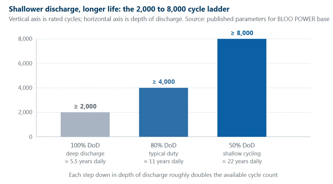
Figure 3 · Cycle ratings are the published parameters for the BLOO POWER BP-BSB base station rack series. The "years" annotations are an arithmetic illustration assuming one full equivalent cycle per day (2,000/365 ≈ 5.5, 4,000/365 ≈ 11.0, 8,000/365 ≈ 21.9) and are not a warranty statement. Any project that will be judged against a warranty should require the testing temperature, the charge and discharge rates and the end-of-life criterion, normally capacity falling to 80 percent SOH, in writing.
This chart also explains why the BMS rewrites total cost of ownership directly. The first layer is discharge-depth management. If the protection strategy lets the bank be driven close to empty on a routine basis, the project is locked into the 2,000-cycle tier. If the strategy lifts the discharge cut-off and holds routine depth of discharge at 80 or 50 percent, the same hardware delivers 4,000 to 8,000 cycles. That is a four-fold spread in life determined by a software policy, at essentially zero marginal cost. The second layer is the ability to realise the rating. Even if the cells could in principle reach 8,000 cycles, weak balancing, inadequate thermal monitoring or a SOC estimate that drifts and drives repeated over-charge or over-discharge will make actual life fall short. The BMS is precisely the component that decides whether the rated life becomes available life.
The third layer is evidence. Most warranty clauses are written as a minimum capacity retention at a stated cycle count and temperature, and SOH is computed and recorded by the BMS. If the BMS cannot count cycles accurately and retain capacity and internal-resistance history with timestamps, the warranty becomes an argument without documentation. The contrast with lead-acid is stark: valve-regulated lead-acid batteries widely used at telecom sites are commonly designed for 500 to 800 cycles at 50 percent depth of discharge, and in real site conditions frequently require replacement within three to four years. Put cycle life and the ability to measure it side by side and the conclusion is straightforward: in a site storage procurement review, the BMS specification deserves the same weight as the cell specification.
Parallel expansion, master/slave roles and current sharing
Site load does not arrive all at once, so expansion is normal and modular paralleling is the standard architecture for site storage. BLOO POWER's low-voltage 48 V rack design supports up to 16 modules in parallel, matching the capacity ladder from small cell sites up to large macro sites. But a parallel architecture imposes a set of requirements on the BMS that did not exist in the lead-acid era, and all three of them are places where commissioning goes wrong.
The first is SOC alignment before paralleling. Before the paralleling contactors close, every module's SOC must be brought within a few percentage points of the others, followed by one complete balancing cycle. The reason is plain physics: two modules at materially different SOC, once connected, drive a large circulating current from the higher-voltage side to the lower, with no load to absorb it - a current that is neither load-limited nor a discharge, and that readily produces heating and protective trips with no external load present at all. The second is master and slave role assignment. With multiple modules in parallel the BMS units need an explicit protocol for aggregation, reporting and decision-making, with one or more units acting as master and the remainder responding as slaves. Without that protocol each module limits current according to its own judgement, and the whole string is held back by the most conservative unit. The third is current sharing. Even after alignment, differences in internal resistance, cable length, contact resistance and cooling position still skew how current divides. Over a long service life the module carrying more current ages faster, which widens the imbalance further.
All three need design-level support in the BMS, not improvised at commissioning. BLOO POWER publishes explicit engineering guidance for parallel configuration: align SOC first, then close the contactors, then run one complete balancing cycle, with SOC, total current and cell voltage uploaded continuously as the required parallel-operation parameters. For an integrator, the practical translation is that a tender document should score the maximum parallel module count, the master/slave protocol description, current-sharing accuracy and the commissioning procedure documentation as separate items, rather than asking generically for "parallel support".
Delivering the backup runtime you specified
Backup runtime is the only metric at a site that is ever genuinely examined. Requirements vary widely: in Chinese network practice, a normal urban base station is typically specified for three to five hours, remote mountain and transmission nodes for eight to ten hours, and major hubs for twelve to twenty-four hours, while in the United States the FCC's withdrawn eight-hour cell-site figure still functions as an industry reference point and California mandates up to 72 hours in high fire threat districts. What matters for this discussion is the persistent gap between the runtime a project calculates and the runtime a site actually delivers. Field surveys have found regional averages well below design intent - one Chinese regional study found average battery backup duration generally under three hours, with individual sites lasting only about ten minutes. That finding is specific to a region and a period and should be read as an illustration of the gap, not as a national average.
Two mechanisms explain most of the gap. The first is that usable capacity is locked by the discharge-depth policy. The second is that the battery's state of charge at the instant the grid fails is not necessarily 100 percent. The first is a configuration question; the second is squarely a BMS question, because if the SOC estimate is optimistic, the operations platform believes the bank is full right up to the moment the outage reveals that it is not.
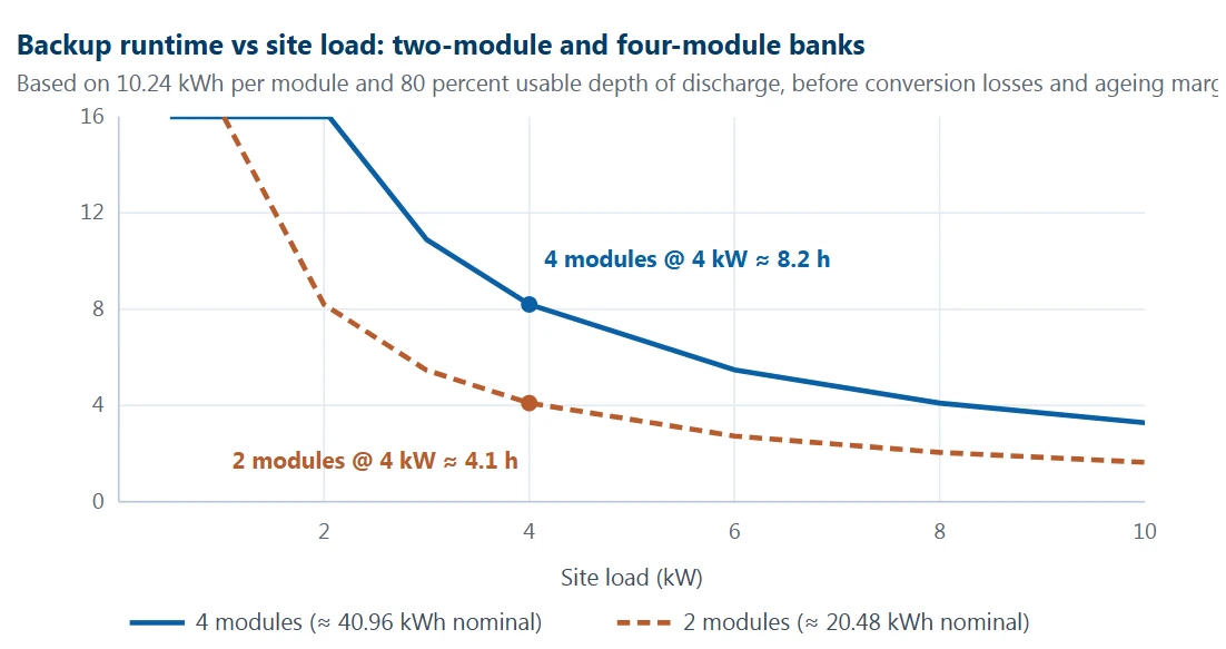
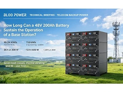
Figure 4 · Calculation basis: 10.24 kWh nominal per module (the 10 kWh tier corresponds to 51.2 V × 200 Ah), 80 percent usable depth of discharge, curves are theoretical and exclude conversion losses, cable losses and ageing margin. BLOO POWER publishes a related reference case: two modules support about 3.9 kW against a three-hour target, and four modules support about 7.8 kW against the same three-hour target, or about 7.8 hours at a 4 kW load. Live projects should size from measured site load, target runtime, a temperature correction factor and an ageing factor rather than from a nominal nameplate.
To actually collect the designed runtime from that chart, the BMS has to get three things right. First, the discharge cut-off policy. Set the cut-off conservatively and usable energy falls noticeably below design, shortening real runtime; set it aggressively and cycle life is spent. That is an explicit trade between today's runtime and tomorrow's life, and it belongs in the project file rather than in a factory default. Second, SOC accuracy. Backup power is only ever cashed in at the instant of an outage, and how full the battery is at that instant rests entirely on the estimate; the difference between a ±2 percent estimator and one drifting ±5 percent or worse is more than ten minutes at multi-hour runtime scale. Third, preservation of cell consistency. If imbalance grows over years of operation, the string hits its cut-off early and delivers less usable energy than nameplate, which returns to the logic of point 03.
It is worth noting where this is heading. Site storage is evolving from pure backup toward backup plus peak shaving, in which the bank charges at low tariff periods and discharges at high ones to trim the electricity bill. The precondition for participating in that kind of dispatch is precisely the pair of capabilities the BMS provides: an accurate SOC and a charge/discharge strategy that can be issued remotely.
The operating economics of unattended sites
Move the view from one site to a network and the value of the BMS is amplified, because site operating cost is structurally dominated by the cost of sending someone to the site. China Tower reported 2.172 million tower sites at the end of June 2026, with cumulative base station build requests above 6.2 million, of which more than 3.28 million were 5G projects; China's Ministry of Industry and Information Technology counted 5.195 million 5G base stations nationally at the end of August 2026, 39.7 percent of all mobile base stations, an increase of 357,000 over the end of the previous year. At that scale, sites have to be designed for unattended operation, and every unplanned visit carries labour hours, a vehicle, the physical risk of working on a rooftop or a mountain site, and possibly temporary generation.
Lead-acid is doubly painful under that cost structure. It requires periodic voltage, internal-resistance and visual inspection, typically every three to six months. And its failure mode drags the whole string with it: a single misbehaving block causes the string to over-charge during charge and to reach cut-off early during discharge, shortening the entire string's discharge time. The BMS changes the ledger in three directions. First, inspection becomes data: with cell voltage, internal-resistance trend, temperature history and cycle count uploaded continuously, an operator can filter for the sites whose consistency is deteriorating and narrow calendar-based inspection to the small set that genuinely needs it. Second, replacement becomes targeted rather than wholesale: with per-cell data it is possible to say which cell is the constraint and how much usable life the string has left, instead of replacing a set because one block failed. Third, generator dispatch becomes calculable: the SOC and remaining runtime that the BMS reports determine whether a generator needs to be dispatched immediately, how many, and how much time margin exists.
Stack those three together and the financial meaning of "fewer unnecessary interventions" becomes concrete. It also explains why BLOO POWER packages the remote monitoring and management platform, the SNMP interface, the event log and a 15-year warranty claim together across the site storage line. In unattended operation, observability and uptime are not features of the product; they are the product.
Compliance evidence, certification and second-life value
The last point is the least technical and the one that most often causes delivery delays or failed acceptance. Lithium entering a telecom site has to satisfy two entirely different categories of requirement, and procurement documents routinely conflate them. The first category is deliverability - whether the shipment may legally leave the factory and travel by air or sea to the project. UN 38.3 is the mandatory transport test for lithium batteries, covering altitude simulation, thermal cycling, vibration, shock, external short circuit, impact, overcharge and forced discharge, and the MSDS documents material safety information; this matters most for remote-site projects where equipment transits several legs. CE and FCC cover electromagnetic compatibility and radio equipment access for the European and United States markets respectively.
The second category is system-level safety and performance evidence, which addresses the battery system itself and normally has to be requested per project as a test report or declaration: IEC 62619 for industrial lithium safety and IEC 62620 for performance; IEC 63056 for energy storage system safety; UL 1973 for stationary batteries and UL 9540A for thermal runaway fire propagation; UL 9540 for the complete energy storage system; and NFPA 855 for installation in North America, alongside local electrical and fire codes and the requirements of the authority having jurisdiction. One detail has to be remembered: UL 9540A is a test method and does not constitute a certification. A datasheet stating "UL 9540A certified" is a signal to ask a follow-up question, and the correct statement is that a UL 9540A report is available, together with the tested state of charge, whether propagation occurred, and the heat release data.
The brand's own published position should be read against that distinction. BLOO POWER's site header and company certificates page list CE, FCC, MSDS, UN 38.3, UL 1973 and IEC 62619, together with ISO 9001, ISO 14001 and ISO 45001 management system credentials and a 15-year warranty claim. In a procurement file, that first group should be treated as the entry threshold and the second group - including any UL 9540A report - should be listed separately as a per-project request item.
There is also a trend worth preparing for now. EU Regulation 2023/1542, in force since August 2023 and fully replacing the old Batteries Directive from August 2025, makes a digital battery passport mandatory from 18 February 2027 for electric vehicle batteries, light means of transport batteries and industrial batteries above 2 kWh - which is exactly the class a telecom site battery sits in. The passport is a live record accessed by a QR code and linked to a unique identifier, carrying capacity, performance, expected lifetime, carbon footprint and end-of-life data; carbon footprint declarations for rechargeable industrial batteries above 2 kWh follow a staged timetable. Put simply, the data the BMS records today is what determines whether this battery can be lawfully, safely and profitably repurposed in five years. A BMS that cannot retain capacity, cycle count and energy-throughput history with timestamps is not only a warranty liability; it is a compliance one.
Table 2 · Overview of BLOO POWER Base Station Modules
Specifications for the BLOO POWER Base Station Module Series (BP-BSB Rack-mount Series · BP-HP Floor-standing Series)
|
Item |
BP-BSB-5KWH-3U |
BP-BSB-7KWH-3U |
BP-BSB-10KWH-3U |
BP-HP-10KWH-B (floor-standing) |
|
Nominal voltage |
48 V / 51.2 V |
48 V / 51.2 V |
48 V / 51.2 V |
51.2 V |
|
Series configuration |
15S / 16S |
15S / 16S |
15S / 16S |
LiFePO4 (LFP) |
|
Rated capacity |
100 Ah |
150 Ah |
200 Ah |
200 Ah |
|
Rated energy |
5 kWh |
7 kWh |
10 kWh |
10,240 Wh |
|
Voltage range |
40–58.4 V |
40–58.4 V |
40–58.4 V |
44.8–58.4 V |
|
Charging method |
CC / CV / CP |
CC / CV / CP |
CC / CV / CP |
CC / CV |
|
Charge / discharge current |
50 A / 50 A |
50 A / 50 A |
100 A / 100 A |
50 A max charge / 100 A max discharge (200 A peak) |
|
Max continuous charge / discharge |
100 A / 100 A |
100 A / 100 A |
200 A / 200 A |
- |
|
Weight |
40 kg / 88 lb |
58 kg / 128 lb |
65 kg / 143 lb |
78 kg / 172 lb |
|
Dimensions (W × D × H) |
440 × 400 × 130 mm (3U) |
480 × 400 × 130 mm (3U) |
500 × 442 × 130 mm (3U) |
480 × 450 × 266 mm |
|
Form factor |
3U rack |
3U rack |
3U rack |
Floor-standing |
|
Operating temperature |
−20 to 65 °C (−4 to 149 °F) |
−20 to 65 °C |
−20 to 65 °C |
Discharge −10 to 55 °C / charge 0 to 55 °C |
|
Communications |
RS485 / CAN |
RS485 / CAN |
RS485 / CAN |
CAN / RS232 / RS485 |
|
BMS capability |
SNMP supported, with a remote monitoring and management system; over-charge, over-discharge, over-current, short-circuit and over-temperature protection; LCD display; compatible with most off-grid and hybrid inverters and charge controllers |
Over-charge and over-discharge protection plus abnormal-condition alarms |
||
|
Cycle life |
≥ 2,000 cycles at 100% DoD · ≥ 4,000 at 80% · ≥ 8,000 at 50%. A separate published figure cites more than 6,500 cycles at 80% DoD with a 15-year design life; the two do not reconcile exactly. |
|||
|
Recommended configuration |
1 module: small cells, DAS, single-band 4G sites · 2 modules: about 3.9 kW against a 3-hour target · 4 modules: about 7.8 kW against a 3-hour target, or about 7.8 hours at a 4 kW load |
|||
Source: published parameters on BLOO POWER base station battery product pages and product knowledge articles. The operating temperature row is the reason this table is worth reading closely: the rack series publishes a single −20 to 65 °C range without separating charge from discharge, while the floor-standing module publishes a discharge window of −10 to 55 °C and a charge window of 0 to 55 °C. Because charging LiFePO4 below 0 °C is prohibited across the chemistry, the charge window is the number a project should be built on. The same product family also publishes a second cycle-life figure that does not reconcile with the depth-of-discharge ladder; projects that will be judged against a warranty should obtain the final confirmed datasheet and third-party test report. The maximum continuous current figures are short-duration BMS limits, and long-term operation should be designed with margin below them.
Where this logic stops working: three boundaries
A technical article that only lists advantages is not worth trusting, so the boundaries need stating plainly. Even a well-specified BMS for telecom base station batteries cannot solve the following three classes of problem.
Problems originating in the cell material and its manufacture. A BMS is a control and algorithm system; it can govern how a battery is used, but it cannot repair an electrode coating defect, a separator flaw or excess moisture in a cell. If a supplier uses cells of unverifiable origin or unscreened second-life cells and pairs them with a generic BMS whose model parameters were never calibrated to that cell, even a well-designed protection layer is working on an unstable foundation. Two things should be confirmed at selection: whether the cell supply is traceable, and whether the SOC and SOH models were calibrated for the exact cell actually used.
Physical constraints beyond configuration capability. If a grid outage lasts longer than the design runtime derived from load and capacity, the BMS can only report the true remaining SOC and execute a protective shutdown; it cannot manufacture energy. Likewise, in an outdoor cabinet below 0 °C a BMS action can only inhibit charging; genuinely charging at low temperature requires a heater, which is a hardware problem rather than a software one.
Interface mismatch cost in existing sites. For a site that already has substantial installed equipment, replacing batteries can run into rectifier output settings that no longer match, network management protocols that do not interoperate, and cabinet space or floor loading limits. A BMS cannot resolve any of these; they are absorbed by adding a data acquisition gateway, reconfiguring the rectifiers or changing the mounting arrangement, and each of those raises total retrofit cost. Setting these three boundaries out during the option study is cheaper than discovering them at commissioning, and it makes the design far easier to defend at review.
Table 3 · The ten loops a BMS has to close
A data list that can be lifted directly into a technical requirement
|
No. |
Monitored / protected |
Sampling and action requirement |
Why it is critical |
Standard / basis |
|
1 |
Cell voltage |
Sample every cell; independent hard thresholds for over-voltage and under-voltage that open the circuit |
Sets both usable string capacity and the safety boundary |
IEC 62619 / UL 1973 |
|
2 |
Cell balancing |
Passive 50–300 mA or active 1–5 A; the balancing strategy must be auditable |
Counters the mismatch that leaves capacity in the pack but out of reach |
Industry literature |
|
3 |
Total voltage and total current |
Continuous sampling for energy accounting and current-limit decisions |
The data foundation for dispatch and peak shaving |
ITU-T L.1221 |
|
4 |
Cell temperature, multi-point |
Cell surfaces plus busbars plus cabinet air; state the number of sampling points |
A 10–15 °C gradient is the main driver of divergent ageing |
UL 9540A propagation logic |
|
5 |
State of charge |
Coulomb counting with full and empty anchor resets, or a model-based estimator |
The precondition for delivering the specified runtime |
Applied Energy 2025 |
|
6 |
State of health and cycle count |
Capacity and internal-resistance history retained with timestamps and exportable |
The evidence base for warranty claims and second-life value |
EU 2023/1542 |
|
7 |
Over-current and short circuit |
Millisecond signal-level interruption, layered with fuses rather than replacing them |
The first electrical line of defence under stepped 5G current |
- |
|
8 |
Low-temperature charge inhibit |
Cut charge current if any cell is below 0 °C, rather than only derating |
Plating damage is permanent, cumulative and can cause an internal short |
Industry literature |
|
9 |
Communications and remote firmware upgrade |
RS485 / CAN as the floor; Modbus and SNMP required to join network management |
Determines whether the site can enter an existing management system at all |
ITU-T L.1221 |
|
10 |
Event log and anti-theft |
Over-voltage, under-voltage, over-current, short circuit, temperature limit and charge inhibit all logged and retrievable |
Attribution, exception-driven dispatch and asset security |
ITU-T L.1221 |
Item 6 is moving from a nice-to-have to a compliance requirement in the European Union: Regulation 2023/1542 introduces carbon footprint declarations and a digital battery passport in stages, requiring capacity, cycle count and energy-throughput history, and the BMS is the only source of that data. The anti-theft element in item 10 is not an addition of our own - ITU-T L.1221 explicitly includes battery and cell-level management and monitoring, including anti-theft provisions, within its scope.
BMS for telecom base station batteries: put these lines in your specification
The seven clauses below can go straight into a tender document or technical agreement as a standalone BMS section. What they have in common is that they are verifiable, refusable and leave no room for ambiguity.
- State the estimation method and its accuracy, not "SOC display provided". Require the supplier to document in writing which SOC method is used (coulomb counting, OCV plus coulomb counting, or a model-based estimator), the anchor events that reset it, the maximum steady-state error across 10 to 35 °C, and the calibration evidence for the specific cell model supplied.
- State the balancing topology and balancing current. Require the passive or active topology, the balancing current, and whether balancing continues during discharge. For sites using second-life cells or cycling shallowly and frequently, require active or hybrid balancing.
- Make temperature sensor count and placement a hard number. Require the number of temperature sensors per module and their positions (cell surface, busbar, cabinet air), and state the criterion and recovery condition for low-temperature charge inhibit.
- List every communication interface and data point. RS485 and CAN on the physical layer; Modbus RTU or Modbus TCP at the application layer; SNMP plus interface documentation if the site must join an existing management platform. Data points must at minimum cover SOC, SOH, total voltage, total current, cell voltage, multi-point temperature, alarms and the event log, with remote firmware upgrade supported.
- Request certifications as two separate lists. The first lists the deliverability credentials the supplier holds (UN 38.3, MSDS, CE, FCC, RoHS). The second requests system-level evidence per project (IEC 62619, IEC 62620, IEC 63056, UL 1973, UL 9540, and a UL 9540A report stating the tested state of charge and whether propagation occurred).
- Tie the warranty to retained data. Require the warranty clause to specify a minimum capacity retention at a stated temperature and cycle count, and require the BMS to export timestamped capacity, internal-resistance and cycle-count history. Without that data the warranty clause cannot be executed.
- Put the parallel commissioning procedure in the deliverables. Require the maximum parallel module count, the master/slave protocol description, current-sharing accuracy, the commissioning sequence - align SOC, close contactors, run one complete balancing cycle - and an acceptance record template.
In one sentence: at an unattended site the BMS is not an accessory to the battery, it is the battery's operating crew. It decides how deep the pack can safely be taken, how accurately its remaining energy can be known, what temperatures it can work in, and whether the operator finds out about a problem before the site goes down.
Related products: BLOO POWER base station modules
The three products below cover the main installation forms from small cells to macro sites and from rack to floor-standing. What they have in common is that the BMS and the communications capability are standard rather than optional.
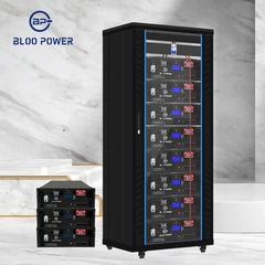
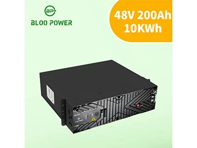
U rack modules for telecom base stations and distributed power systems, built on prismatic LiFePO4 cells. Nominal voltage 48 V / 51.2 V, 15S or 16S configuration, capacities of 100 Ah, 150 Ah and 200 Ah. An integrated battery management system provides over-charge, over-voltage, over-discharge, over-current, short-circuit and high-temperature protection, reports over RS485 and CAN, and supports SNMP with a remote monitoring and management system.
Operating temperature −20 to 65 °C (−4 to 149 °F)
Cycle life ≥ 2,000 at 100% DoD · ≥ 4,000 at 80% · ≥ 8,000 at 50%
Communications RS485 / CAN, SNMP supported
Sizing reference 1 module for small cells and DAS; 4 modules give about 7.8 hours at a 4 kW load
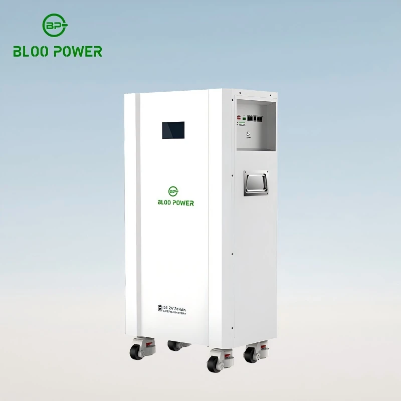
BP-HP-10KWH-B floor-standing module
For sites with more installation space and a higher cycle-life requirement. Rated energy 10,240 Wh, working voltage 44.8–58.4 V, internal resistance not exceeding 30 mΩ, LiFePO4 chemistry with an integrated BMS that alarms and protects under abnormal conditions and communicates over CAN, RS232 and RS485.
- Dimensions and weight 480 × 450 × 266 mm, 78 kg (172 lb)
- Temperature window Discharge −10 to 55 °C / charge 0 to 55 °C
- Cycle life Published figures include 8,000 cycles at 100% DoD and
- 6,500 cycles at 80% DoD - confirm the applicable figure
- Best fit Floor-standing battery cabinets and sites needing larger capacity per unit
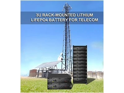
A low-voltage parallel architecture designed for build-first, expand-later projects, supporting up to 16 modules in parallel. The BMS interoperates with mainstream inverters, and SNMP-capable 3U and 4U rack formats are available across several capacity tiers, so a site can be expanded in steps as load grows instead of being over-provisioned at day one.
Parallel limit Up to 16 modules
System voltage Low-voltage 48 V, with high-voltage options available
Management BMS interoperates with mainstream inverters; SNMP models
connect directly to network management
Sizing advice Work backwards from target runtime, then load, then module
count - not from footprint
|
Turn this list into a specified selection
See the base station battery range
Read the off-grid telecom solar-plus-storage guide
|
Send Inquiry