




















How to Parallel Rack-Mounted Batteries to Achieve the Required Capacity?
Oct 12, 2026
Leave a message

|
What this guide answers
|
Why rack-mounted plus parallel became the default building block
Energy storage moved from engineered-per-project to assembled-from-modules over the past decade, and the 19-inch rack became the shared physical interface. A 3U module - 131 mm tall - carries a fixed capacity in the 5 kWh class, so the capacity question reduces to one decision: how many units to parallel. The IEA's Global Energy Review 2026 put global battery storage additions at roughly 108 GW in 2025, about four fifths utility-scale and about 90% LFP. The United States added a record 18.9 GW / 51 GWh, and Europe reached 102.7 GW installed, more than its nuclear fleet.
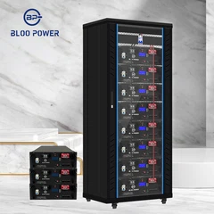
The architecture, and the BESS battery energy storage manufacturer behind it, matter more than any single datasheet. BLOO POWER, the brand of Zhengde Hanyuan (Shenzhen) Technology Co., Ltd., builds its rack series that way, spanning 3 kWh to 500 kWh from a common 3U form factor. The same logic drives sourcing: a China lithium-ion battery for solar energy storage with verifiable IEC 62619 and IEC 62620 reports is worth more than a cheaper pack with untraceable test data.

What paralleling actually changes: voltage holds, capacity and current stack
The first rule: voltage is set by cell chemistry and string length, capacity by the count. Join N identical rack modules positive-to-positive and negative-to-negative and nominal voltage stays that of a single unit - commonly 51.2 V, sixteen LFP cells in series - while capacity and energy scale by N. Series does the opposite, raising voltage and leaving capacity unchanged. Treating the two as interchangeable is the most common error in datasheet review, and why the phrase lithium battery energy storage system is used so loosely.
Vbank = Vmodule
Cbank(Ah) = Cmodule(Ah) × N Ebank(kWh) = Emodule(kWh) × N
Ibank,max = Σ Imodule,max (downstream devices bind first)
Take a BLOO POWER BP-HP-5KWH-3U at 51.2 V / 100 Ah / 5.12 kWh. Parallel four and the bank still nominates 51.2 V, but capacity becomes 400 Ah and 20.48 kWh. One caveat is routinely missed: paralleling raises the DC power the battery can supply, not the AC power the inverter delivers, so a 5 kW inverter still caps AC output at 5 kW. Depth of discharge and round-trip efficiency must also be applied: at 80% DOD some 20% of nameplate energy is never released, so a design based on nameplate times count alone delivers 15% to 25% less backup than promised. Four units of a 10kwh energy storage lithium ion battery reach 40.96 kWh; the same target needs eight 5.12 kWh units.
Sizing backwards from the required capacity: a formula you can re-run
The question from a project team is rarely "what do four modules equal?" It is "I need 5 kW backed up for 8 hours - how many modules do I parallel?" Answer it with the derating terms inside the arithmetic, or the count always comes out low. Derive theoretical energy from load power and duration, divide successively by round-trip efficiency, depth of discharge, a temperature factor and a lifetime fade margin, then divide by module nameplate energy - the reliable answer to how to parallel rack-mounted batteries for a target capacity.
Edesign = ( P × t ) ÷ ( ηrt × DOD × ktemp × kdegra )
N = ⌈ Edesign ÷ Emodule ⌉ (verify N ≤ the vendor's parallel maximum)
Using conservative factors - ηrt = 0.92, DOD = 0.80, ktemp = 0.95, kdegra = 0.95 - a 5 kW × 8 h load of 40 kWh maps to 60.2 kWh. 5.12 kWh BP-HP-5KWH-3U modules therefore require 12 units; 10.24 kWh BP-HP-10KWH-3U modules need only 6. Half the module count halves terminals, cable runs, communication nodes and labour - the most direct cost lever at specification stage.
Table 1 · Parallel count against system capacity and backup duration (51.2 V platform, 80% DOD, 92% round-trip efficiency)
|
Parallel units |
Capacity, 5.12 kWh modules |
Capacity, 10.24 kWh modules |
String capacity |
Backup at 5 kW load |
|
1 unit |
5.12 kWh |
10.24 kWh |
100 Ah |
≈ 0.75 h |
|
2 units |
10.24 kWh |
20.48 kWh |
200 Ah |
≈ 1.5 h |
|
4 units |
20.48 kWh |
40.96 kWh |
400 Ah |
≈ 3.0 h |
|
8 units |
40.96 kWh |
81.92 kWh |
800 Ah |
≈ 6.0 h |
|
16 units |
81.92 kWh |
163.84 kWh |
1,600 Ah |
≈ 12.1 h |
Backup duration is net of 80% DOD and 92% round-trip efficiency; for another load power, scale duration inversely.

Figure 1 - Parallel units against bank capacity. Nominal capacity grows linearly with unit count, but usable energy must still be discounted for depth of discharge and round-trip efficiency. The curve stops at 16 units, the published parallel maximum.
|
IN PRACTICE · Never accept "usable capacity = nameplate × count" in a proposal. Ask for the four derating factors as written numbers. |
Current sharing and circulating current: where parallel systems actually fail
In an ideal bank each of N modules carries 1/N of the current. In reality any difference in terminal voltage, internal resistance or loop length redistributes it, and the most dangerous instant is not steady-state operation but contactor closing. With a pre-connect differential ΔU and total loop resistance Rloop, the instantaneous circulating current is I = ΔU ÷ Rloop. At a realistic on-site 20 mΩ for the complete loop a 1 V differential produces 50 A, 3 V produces 150 A and 5 V approaches 250 A. None of it passes through the load; it circulates between strings and converts entirely into heat, enough to oxidise lugs, weld contactor tips or trip the BMS.
The subtler problem is persistent imbalance. Take two parallel branches whose cable runs differ by 20%: at discharge currents in the hundreds of amperes the impedance difference pushes more current into the shorter branch, which cycles deeper, runs hotter and fades faster. Fading raises its internal resistance, so current redistributes again and loads the tired string harder still; after three years the state-of-charge difference can reach double-digit percentages, and the usable capacity of the bank is pinned to the weakest branch. The countermeasures are deterministic: equal-length branch cabling, a symmetrical-takeoff busbar, per-string breakers and fuses, a pre-connect voltage check and active balancing.
Iinrush ≈ ΔU ÷ Rloop ( ΔU = terminal voltage difference before closing, Rloop = full loop resistance )

Figure 2 - Pre-connect differential against inrush current. Computed from I = ΔU ÷ Rloop. Higher loop resistance limits inrush but raises voltage drop during discharge, so drive the pre-connect differential below 0.5 V rather than adding resistance.
|
Commissioning procedure: before closing any string contactor, measure open-circuit voltage string by string and hold the spread within 0.5 V; where that is not possible, use the BMS pre-charge circuit to cap inrush below 10% of rated string current. |
BMS master–slave addressing: the real ceiling on parallel count
Engineers routinely read "maximum 16 parallel units" on a datasheet and assume chemistry or cell capability sets it. It does not: sixteen is a communication and addressing limit. Every module's BMS must hold a unique address, usually set by a DIP switch or allocated by a host controller, and the master must poll every slave's voltage, current, temperature, state of charge and alarms within a bounded cycle before reporting the aggregate to the power conversion system. When address bits run out, CAN identifiers crowd, or the polling cycle grows long enough to delay protection action, the architecture has hit its ceiling. BLOO POWER publishes 16 for its rack series; some vendors state 15, others 32 or 64.
Two things constantly conflated here must be separated: electrical paralleling and communication paralleling are not the same operation. If the communication link is misconfigured, the power conversion system may see data from one module or none, and protection degenerates into blind charging and discharging: no unique address, no master, no verified protocol, no derating. The BLOO POWER rack series exposes RS232, RS485 and CAN simultaneously - CAN for closed-loop inverter communication, RS485 for inter-module networking, RS232 for local commissioning. A 10kwh energy storage lithium ion battery module halves the number of addresses and firmware images to keep consistent as the bank grows.
|
The most common trap: a connected physical layer is not a working protocol - CAN needs identifier allocation, frame format and bitrate to match.
|
Busbars, cabling and protection: redesigning the DC side
Once the unit count is fixed, current adds up and every downstream conductor and protective device must be recalculated. Take 16 units of BP-HP-5KWH-3U: each BMS publishes a 100 A maximum continuous discharge, so the arithmetic sum is 1,600 A - and no realistic system pushes 1,600 A through one cable. Consolidate at string level: each module feeds the in-string busbar through a conductor sized for its own rated current, and a string breaker plus a high-speed fuse protect and isolate the whole string, so one string fault trips its own devices and leaves the rest of the system online. That is why the protection architecture, not the cell, sets the real availability of a lithium battery energy storage system.
Conductor selection must satisfy ampacity, voltage drop and short-circuit withstand together. Hold total DC loop voltage drop within 1% to 2% of nominal; beyond that the inverter raises a low-voltage alarm before the bank is empty. Protection must be DC-rated: the breaker's interrupting rating must cover the maximum prospective short-circuit current, and fuses should be DC high-speed types such as Class T, because an AC fuse does not extinguish a DC arc. Torque every terminal to specification - under-torqued terminations are the most common chronic failure in paralleled banks, and a BESS battery energy storage manufacturer that prints terminal torque values has seen that failure.
Table 2 · Key electrical parameters and selection boundaries for parallel capacity expansion
|
Design item |
Recommended value / boundary |
Why it matters |
|
Pre-connect terminal voltage spread |
≤ 0.5 V (target); pre-charge required at ≥ 1 V |
Sets inrush current; see Figure 2 |
|
Loop cable length |
Equal per string, spread ≤ 5% |
Length difference drives persistent imbalance |
|
DC voltage drop |
≤ 1%–2% of nominal |
Excess drop triggers low-voltage alarms |
|
String protection |
DC breaker plus high-speed DC fuse (Class T) |
Isolates one string fault without tripping the bank |
|
Pre-charge / current limiting |
Cap inrush below 10% of rated string current |
Protects contactor tips and semiconductors |
|
Communication link |
CAN (inverter) / RS485 (module network) / RS232 (commissioning) |
Electrical and communication paralleling must both be valid |
Ampacity and voltage-drop practice follows the DC provisions of IEC 60364 and the NEC; confirm final values with the project electrical engineer.
Thermal management and temperature uniformity
In a paralleled bank, capacity adds but life multiplies - and it is set by the hottest unit. Lithium-ion fade is strongly temperature dependent, and IEC 62619 makes the relationship concrete in its endurance grades: not less than 80% of cycle life retained at 45 °C for the standard grade, 70% for the extended grade and 60% at 55 °C for the extreme grade. The same cell in a well-ventilated battery room and in the top tier of a sealed cabinet can differ by more than thirty percent in delivered cycle count, so any lithium battery energy storage system specification that omits a temperature-uniformity requirement is incomplete.
Rack cabinet thermal design therefore rests on three rules. Control the internal spread: the inlet-to-outlet air difference across the top and bottom modules should not exceed 2 to 3 °C. Reserve physical space: industry practice leaves roughly 20% of cabinet positions empty, which simplifies later additions and prevents blocked airflow. Move to liquid cooling as power density rises: past roughly 200 kWh per cabinet, or under continuous high-rate cycling such as data-centre UPS duty, air cooling can no longer hold cell-to-cell spread inside the ideal band. BLOO POWER's commercial line already applies liquid cooling on its 261 kWh / 125 kW cabinet so that all paralleled units age in step. UL 9540:2023 also requires coolant leak detection.
Compliance and safety: UL, NFPA, IEC and the EU Battery Regulation
Once a parallel design clears technical review the next gate is compliance, and four layers of documents confuse people. UL 1973 covers product safety for stationary batteries from cell through rack. UL 9540 certifies the complete system as an assembly - battery, BMS, power conversion and enclosure evaluated together. Its third edition, ANSI/CAN/UL 9540:2023, added AC and DC system definitions, capacity escalation via large-scale fire testing, explosion protection aligned with NFPA 68 and 69, an 85 dBA noise limit, warning communication above 500 kWh and coolant leak detection (Table 3). UL 9540A is not a certification but a test method for thermal runaway fire propagation, in four tiers from cell to installation; its fifth edition was published on 12 March 2025.
NFPA 855 converts test data into enforceable separation, capacity and fire-protection requirements: 50 kWh for an indoor single unit, 0.914 m (3 ft) unit separation and a 600 kWh lithium-ion ceiling, with denser layouts permitted on UL 9540A evidence (Table 3). IEC 62619 is the safety requirement for industrial lithium cells and batteries, including an Annex B functional safety assessment requiring redundant BMS protection logic. IEC 62620 is the performance standard - not less than 60% of rated capacity after 500 cycles - and European and Australian warranty contracts frequently cite it. IEC 62933-5-2 covers grid connection and UN 38.3 is mandatory for cross-border shipment.
Since 2024 the European Union has added a further layer that changes what a BESS battery energy storage manufacturer must document. Regulation (EU) 2023/1542 has applied since 18 February 2024: Annex V technical documentation for stationary storage from 18 August 2024, labelling from 2026, and a mandatory battery passport for industrial batteries above 2 kWh from 18 February 2027, with the BMS holding state of health, cycle count and remaining useful life data. What a vendor holds is not what a buyer must request: BLOO POWER publishes UN 38.3, MSDS, CE, FCC and RoHS, while a North American project also needs UL 1973 and a UL 9540A report.
Table 3 · Standards map for rack-mounted parallel battery banks: scope, key requirements and what to request
|
Standard |
Layer |
Key requirement / published data |
|
UL 1973 |
Product safety (cell to rack) |
Overcharge, short circuit, crush and thermal abuse |
|
UL 9540 |
System-level certification |
Battery + BMS + conversion + enclosure; AC/DC definitions, fire-test capacity escalation, 85 dBA, EWCS at ≥ 500 kWh, leak detection |
|
UL 9540A |
Test method (not a certification) |
Four tiers, cell → module → unit → installation; propagation boundary and gas volume; 5th edition, 12 March 2025 |
|
NFPA 855 |
Installation standard |
Indoor single unit ≤ 50 kWh; separation ≥ 0.914 m; system ≤ 600 kWh; hazard mitigation analysis |
|
IEC 62619 / 62620 |
Industrial lithium safety and performance |
Annex B functional safety; ≥ 60% capacity after 500 cycles |
|
EU 2023/1542 |
EU market regulation |
Annex V file from 18 Aug 2024; labelling from 2026; passport above 2 kWh from 18 Feb 2027 |
Consolidated from UL, NFPA and IEC standard texts and EU Regulation 2023/1542. NFPA 855 values are general provisions; projects may differ following UL 9540A data and local code.
When not to parallel: five hard boundaries
Parallel capacity expansion has firm failure boundaries, and crossing one is not degraded performance - it is a safety event. The first red line is mixing brands or batches: different manufacturers implement different BMS protection logic, balancing strategies and charge cut-off conditions, so paralleling them onto one busbar puts two control strategies in competition over the same voltage band. The second is mixing old and new: an older module with 3,000 cycles behind it, paralleled with a new one, is over-discharged and over-charged relative to its companion because of internal resistance mismatch, which accelerates its failure and drags the bank's usable capacity down to the older unit's level.
The third boundary is capacity mismatch - direct paralleling is avoided once single-unit capacity differs by more than about 10%, because current distribution persistently favours the smaller, higher-resistance unit. The fourth is cross-voltage architecture mixing: a 48 V or 51.2 V rack module and a 200 V to 800 V string need a DC/DC converter or a separate PCS input channel. The fifth, and the most widely misread, is that a vendor's maximum parallel count is a system-level limit, not a battery-level limit, jointly constrained by BMS network capacity, busbar ampacity, breaker interrupting rating, inverter DC input rating and the installation code.
|
One sentence to remember the boundary: the feasible parallel limit is the minimum of seven values - battery, BMS, power conversion, busbar, protective devices, rack structural rating and local code. |
Economics: from tender prices to levelized cost of storage
Capacity decisions eventually land on money, and the Chinese telecom backup market offers a rare public price anchor. The China Tower Jiangsu 2026 off-peak LFP battery tender (reference ZJZT-2026-13969) set a maximum bid price excluding tax of ¥4,400 per 100 Ah pack and ¥7,250 per 200 Ah pack, against an estimated procurement value of ¥45.3734 million with a 60-month warranty. The candidate announcement showed the first-ranked bidder at ¥3,850 and ¥6,850 - competition pulling realised prices roughly 5% to 15% below the ceiling.
A 100 Ah pack is approximately 5.12 kWh, so the ¥4,400 ceiling works out to about ¥859/kWh and the winning bid to about ¥752/kWh; a 200 Ah pack is approximately 10.24 kWh, giving ¥708/kWh and ¥669/kWh. At ¥7.15 per US dollar that is roughly $105/kWh and $94/kWh - the larger pack materially cheaper per kilowatt-hour on an identical platform, which is the economic mechanism behind Section 03. Combined with the 8,000 cycles at 80% DOD published for the BLOO POWER rack series, levelized cost per delivered kilowatt-hour falls to a small fraction of purchase price.

Figure 3 - A public price anchor for rack batteries. China Tower Jiangsu 2026 off-peak LFP battery tender documentation. On an identical voltage platform the 200 Ah pack works out roughly 11% cheaper per kilowatt-hour than the 100 Ah pack.
Five reference configurations by application
Residential storage: two to four units
Residential loads typically run 3 kW to 10 kW, from maximising solar self-consumption to covering a whole night. A 5 kW evening load for six hours corresponds to about 40 kWh of design energy, which four 10.24 kWh modules cover. Space and noise dominate, so slim 2U (88 mm) or 3U (131 mm) modules suit best - the BLOO POWER BP-HP-5KWH-2U is 88 mm tall and 40 kg. This is where a 10kwh energy storage lithium ion battery module earns its place as the standard unit, and where a 10kWh lithium-ion battery for solar self-consumption and backup becomes a verifiable requirement rather than a marketing phrase.
Commercial and industrial peak shaving: design at cabinet level
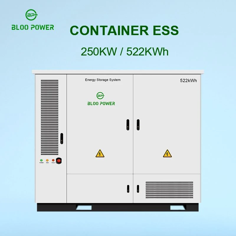
C&I revenue comes from peak-to-valley spreads and demand management, with single-cabinet energy usually between 100 kWh and 500 kWh. At that scale module-granularity design becomes uneconomic: terminals, communication nodes and cable costs grow with unit count. Lift paralleling to string and cabinet level - modules series-connected into a high-voltage string, several strings paralleled onto the PCS DC side, each string with its own BMS slave and protection. This is the logic behind the BLOO POWER commercial line: the 261 kWh / 125 kW liquid-cooled cabinet and the 250 kW / 522 kWh system. For a US project, confirm that the configuration tested to UL 9540A matches the local fire code - a UL 9540A tested battery cabinet for commercial and industrial storage is what unlocks a denser, cheaper layout.
Telecom backup: standardised 48 V and 51.2 V packs
Telecom sites are the most standardised parallel application in the market, and the China Tower Jiangsu 2026 tender procured explicitly at 100 Ah and 200 Ah pack level. Site space is fixed and maintenance happens only on scheduled visits, so the battery must fit an existing 19-inch rack and match the existing DC platform. Typical configurations run one to four parallel units for 5.12 to 20.48 kWh, discharging one to two hours per daily peak window - and because the standardised unit is a 48V 100Ah LiFePO4 server rack battery with CAN bus monitoring, spares and replacement are straightforward across a distributed fleet.
Data centres and UPS: short duration, high rate, reliability first
Data-centre UPS duty inverts these priorities: backup duration is often only five to fifteen minutes, but discharge rate, fault isolation and redundancy requirements are extreme. Here paralleling exists for current sharing and redundancy rather than capacity - multiple units maintain output when one fails while keeping each unit's discharge rate gentle, which requires string-level fusing and breakers. The IEA reported battery UPS additions, dominated by data centres, growing roughly 30% in 2025 to about 45 GW.
Off-grid and microgrid: buy expansion flexibility early
Off-grid and microgrid projects share one defining trait: load growth cannot be predicted. Meet today's demand and add units later - start with four, add two to four more as load grows, without replacing the cabinet or busbar. Reserve expansion capacity at design stage: spare busbar tap points, roughly 20% empty cabinet positions, and conductors sized for the final capacity.
From parallel modules to liquid-cooled cabinets and containers
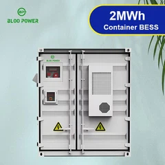
As capacity requirements rise, the level at which rack-mounted batteries are paralleled moves upward: module to module, then modules series-connected into a string, then strings, cabinets and containers. Each step brings more capacity and a larger blast radius for a single failure, so every level needs a matching protection upgrade: string breakers, DC fuses, busbar segmentation and independent monitoring. BLOO POWER's 250 kW / 522 kWh liquid-cooled system uses a 260S2P LFP architecture with 314 Ah cells and 832 V nominal DC, and the 500 kW / 2 MWh system is customisable from 215 kWh to 2 MWh. LFP makes a 4-hour rack bank feasible today, while an advanced lithium-ion sulfur battery for high energy storage is aimed at the far longer, weight-critical duty above it.
Choosing between low voltage and high voltage is a trade between current and complexity. A 48 V / 51.2 V low-voltage architecture is standardised, allows direct module paralleling and shares spares across projects; the price is higher current for the same power, driving up conductor cross-section, voltage drop and device ratings, so it fits below roughly 100 kWh. A 200 V to 800 V high-voltage architecture carries far less current, cutting conductor and loss costs; the price is series-connected BMS slaves and high-voltage insulation design. The dividing line: below 100 kWh choose low-voltage paralleling; above 200 kWh choose high-voltage string paralleling. A China lithium-ion battery for solar energy storage supplier covering both formats from one quality system removes a category of integration risk.
BLOO POWER rack-mounted and cabinet product line
Rack-mounted · 3U · 16S
BP-HP-5KWH-3U
1.2 V / 100 Ah / 5.12 kWh, 8,000 cycles at 80% DOD, 100 A maximum continuous discharge, 60 kg, 550 × 442 × 131 mm, up to 16 units in parallel.
Rack-mounted · 2U · slim
BP-HP-5KWH-2U
48 V / 100 Ah / 5 kWh, only 88 mm tall and 40 kg, 8,000 cycles at 80% DOD, up to 16 units in parallel. Optimised for space-constrained residential cabinets and retrofits.
Commercial · liquid-cooled
261 kWh / 125 kW liquid-cooled cabinet
Grade-A LFP cells, liquid-cooling thermal management and integral cabinet fire protection, 8,000-plus cycles, UN 38.3 / MSDS / CE / IEC / FCC. Lifts paralleling from module to cabinet level.
Cell chemistry choices: LFP today, sulfur and liquid-metal cells for what comes next
Every architecture discussed so far assumes LFP cells, because that is what rack-mounted storage is built from today. LFP wins on the metrics that matter for a stationary, frequently cycled, safety-constrained asset: high thermal runaway onset, low gas yield per ampere-hour, 6,000 to 8,000 cycles at 80% depth of discharge, and material cost insulated from nickel and cobalt price swings - which is why LFP held roughly 90% of deployments in 2025.
On the high-energy side sits sulfur chemistry. An advanced lithium-ion sulfur battery for high energy storage targets a theoretical 2,600 Wh/kg and a practical 500 Wh/kg - two to three times a commercial LFP cell; Ah-level pouch cells have demonstrated 622 Wh/kg. Lithium-ion sulfur cell energy density for long-duration storage has therefore crossed the point where a designer should track it. The obstacles are documented just as well: polysulfide shuttle, roughly 80% volume expansion and lithium-metal anode instability. It belongs in a roadmap, not a bill of materials.
At the other extreme sits the long-duration, cost-driven family, and sulfur chemistry and liquid metal cells for long-duration grid storage sit outside the rack-mounted mainstream for opposite reasons: one sacrifices cost and cycle life for energy density, the other sacrifices energy density for cost and cycle life. The lithium antimony lead liquid metal battery for grid-level energy storage is the clearest published example - liquid lithium, molten-salt electrolyte and liquid antimony–lead electrodes self-segregating into three layers with no separator, delivering 98% Coulombic and 73% round-trip efficiency at 450 °C, with retention above 85% projected after ten years of daily cycling. The catch is temperature: a lithium antimony lead liquid metal battery for grid-level energy storage must be held at 450 °C to 500 °C, so it carries continuous thermal management and a parasitic heating load - credible on cost and cycle life, pre-scale on manufacturing, complementary to LFP rather than a replacement.
Table 4 · Chemistry comparison for stationary storage: what each family is good at, and where it does not fit
|
Attribute |
LFP (today's rack standard) |
Lithium-ion sulfur (high energy) |
Lithium antimony lead liquid metal (grid level) |
|
Cell-level specific energy |
Roughly 160–200 Wh/kg |
500 Wh/kg target; 622 Wh/kg in Ah-level pouches |
Low per mass; heavy by design |
|
Typical discharge duration |
2–4 h |
4–8 h (projected) |
4–24 h |
|
Cycle life at high DOD |
6,000–8,000 cycles at 80% DOD |
Prototype scale; decay rates still being reduced |
> 450 full-depth cycles; > 85% retention projected after 10 years |
Sulfur figures from peer-reviewed benchmarking; liquid-metal figures from the Li||Sb–Pb study in Nature. Values describe technology families, not products.

Figure 4 - Where each chemistry fits. Positions are indicative of technology families on the two axes that decide most stationary storage specifications: discharge duration and mass per unit of energy.
Writing parallel design into your procurement specification
Compressing the preceding sections into an executable procurement list speeds up technical review and commercial negotiation. The seven clauses below can go straight into a request for quotation as requirements the supplier must answer in writing, and they are an effective screening test for a BESS battery energy storage manufacturer.
- State the load and the backup target, not just a capacity figure. Provide load power in kW, backup duration, the minimum acceptable DC bus voltage and the ambient temperature range, then require the module-count derivation to be shown.
- Lock the voltage platform and the paralleling level. Specify whether the design is 48 V / 51.2 V low-voltage module paralleling or high-voltage string paralleling, and whether it occurs at module, string or cabinet level.
- Require written confirmation of the maximum parallel count and its basis. Reject vague statements such as "supports paralleling." Demand a specific number and which constraint binds it.
- Require communication compatibility confirmation for the named inverter. Obtain a parameter table covering protocol (CAN / RS485 / RS232), frame format, bitrate and address allocation, plus written confirmation of closed-loop communication.
- Request the test report list, separating the two categories. Distinguish what the vendor already holds, such as UN 38.3, CE, FCC and RoHS, from what the project requires, such as UL 1973, UL 9540A, IEC 62619 and IEC 62620.
- Write temperature limits into the contract. Require the minimum charging temperature to be stated explicitly; charging a lithium-ion cell below 0 °C causes irreversible lithium plating.
- Agree the expansion conditions and spares consistency. Record that future expansion will use the same model and firmware version, and that busbar tap points and roughly 20% of cabinet positions remain available.

Need a parallel battery bank sized for your project?
Send our engineering team the load power, backup duration, target inverter model and installation ambient temperature. BLOO POWER will return module selection, parallel unit count, busbar configuration and the compliance report list for your market, customisable from 3 kWh to 500 kWh.
Send Inquiry